4 speed/torque control switching function, Torque control function settings: d5-01, Frequency reference and speed limit – Yaskawa G5HHP Drive User Manual
Page 190
Advanced Operation
7.3.4 Speed/Torque Control Switching Function
7 - 26
•
When the input terminal is used for torque reference:
A 0 V (4 mA) input indicates a torque reference that is 100% of the motor’s rated torque.
•
When the input terminal is used for torque compensation:
A 0 V (4 mA) input indicates a torque compensation that is 100% of the motor’s rated torque.
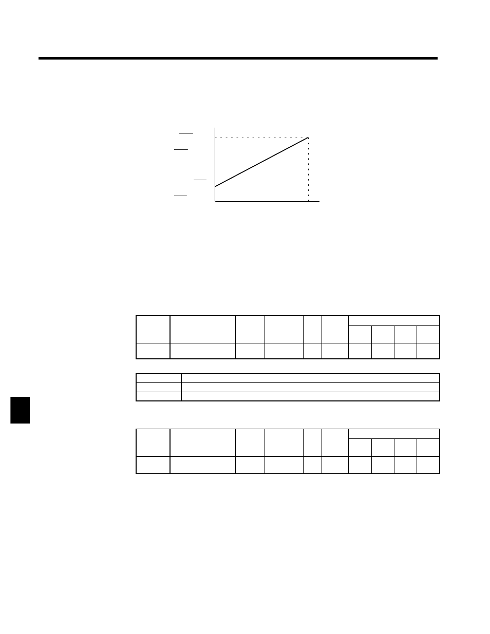
Input voltage
(Input current)
0 V
(4 mA)
10 V
(20 mA) Use the current values shown in pa-
rentheses when current input has
been selected.
Max. frequency × Gain
100
Max. output frequency × Bias
100
Rated torque × Gain
100
Rated torque × Bias
100
Reference value
Fig 7.12
Analog Input Gain and Bias Settings
7.3.4 Speed/Torque Control Switching Function
It is possible to switch between speed control and torque control when one of the multi-function inputs
(H1-01 to H1-06) is set to 71 (Speed/Torque Control Change). Speed control is performed when the input
is OFF and torque control is performed when the input is ON.
J
Torque Control Function Settings: d5-01
User
Change
during
Setting
Factory
Valid Access Levels
User
Constant
Number
Name
g
during
Opera-
tion
Setting
Range
Unit Factory
Setting
V/f
Control
V/f with
PG
Open
Loop
Vector
Flux
Vector
d5-01
Torque control selec-
tion
x
0, 1
--
0
x
x
x
A
D
Settings
Setting
Function
0
Speed control (controlled by C5-01 to C5-07)
1
Torque control
D
Set constant d5-01 to 0 (speed control) when using the speed/torque control switching function.
J
Setting the Speed/Torque Control Switching Timer: d5-06
User
Change
during
Setting
Factory
Valid Access Levels
User
Constant
Number
Name
g
during
Opera-
tion
Setting
Range
Unit Factory
Setting
V/f
Control
V/f with
PG
Open
Loop
Vector
Flux
Vector
d5-06
Speed/torque control
switching timer
x
0 to 1000
ms
0
x
x
x
A
D
This setting specifies the delay (0 to 1,000 ms) between a change in the multi-function input (ON →
OFF or OFF → ON) and the corresponding change in the control mode. The timer setting is effective
only when 71 (Speed/Torque Control Change) has been set in one of the multi-function inputs (H1-01
to H1-06).
D
During the timer delay, the value of the 3 analog inputs will retain the values they had when the ON/OFF
status of speed/torque control switching signal was changed. Use this delay to make any preparations
for the change in the control mode.
J
Frequency Reference and Speed Limit
The frequency reference (during speed control) is set with b1-01 (Reference Selection).
The speed limit (during torque control) is set with d5-03 (Speed Limit Selection).
It is possible to assign the frequency reference and speed limit functions to the same analog input terminal
(36 or 39).
7