3 operation errors – Yaskawa G5HHP Drive User Manual
Page 318
Troubleshooting
9.1.3 Operation Errors
9 - 8
9.1.3 Operation Errors
After the constants have been set, an operation error will occur if there is an invalid setting or a contradiction
between two constant settings.
It won’t be possible to start the Inverter until the constants have been set correctly. (The minor fault output and
fault contact output will not operate, either.)
When an operation error has occurred, refer to the following table to identify and correct the cause of the errors.
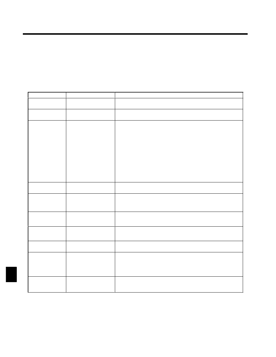
Table 9.3 Operation Error Displays and Incorrect Settings
Display
Meaning
Incorrect settings
OPE01
kVA Selection
Incorrect Inverter capacity
setting
The Inverter capacity setting doesn’t match the Unit. (Contact your Yaskawa repre-
sentative.)
OPE02
Limit
Constant setting range error
The constant setting is outside of the valid setting range.
OPE03
Terminal
Multi-function input selection
error
One of the following errors has been made in the multi-function input (H1-01 to
H1-06) settings:
S
The same setting has been selected for two or more multi-function inputs.
S
An up or down command was selected independently. (They must be used together.)
S
The up/down commands (10 and 11) and Accel/Decel Ramp Hold (A) were selected
at the same time.
S
Speed Search 1 (61, maximum output frequency) and Speed Search 2 (62. set fre-
quency) were selected at the same time.
S
External Baseblock NO (8) and External Baseblock NC (9) were selected at the same
time.
S
The up/down commands (10 and 11) were selected while PID control (b5-01) was
enabled.
S
The Terminal 36/39 Switch (1F) was selected, but the terminal 39 function selector
(H3-09) wasn’t set to frequency reference (1F).
OPE05
Sequence Select
Option Card selection error
The Option Card was selected as the frequency reference source by setting b1-01 to
3, but an Option Card isn’t connected.
OPE06
PG Opt Missing
Control method selection er-
ror
S
V/f control with PG feedback was selected by setting A1-02 to 1,but a PG Speed Con-
trol Card isn’t connected.
S
Flux vector control was selected by setting A1-02 to 3, but a PG Speed Control Card
isn’t connected.
OPE07
Analog Selection
Multi-function analog input
selection error
S
The same setting (other than 1F) has been selected for H3-05 and H3-09.
S
An A1-14B Analog Reference Card is being used and F2-01 is set to 0, but a multi-
function input (H1-01 to H1-06) has been set to Option/Inverter Selection (2).
OPE08
Elevator Table
Constant selection error
A setting has been made that is not required in the current control method.
Ex.:
A function used only with flux vector control was selected for open-loop
vector control.
OPE10
V/f Ptrn Setting
V/f data setting error
Constants E1-04, E1-06, E1-07, and E1-09 do not satisfy the following conditions:
S
E1-04 (FMAX) ≧ E1-06 (FA) ≧ E1-07 (FB) ≧ E1-09 (FMIN)
OPE11
CarrFrg/On-Delay
Constant setting error
One of the following constant setting errors exists.
S
The carrier frequency upper limit (C6-01) > 5 KHz and
the carrier frequency lower limit (C6-02) ≧ 5 KHz.
S
The carrier frequency gain (C6-03) > 6 and (C6-01) > (C6-02).
S
Upper/lower limit error in C6-01 to 03 or C8-15.
ERR
EEPROM R/W Err
EEPROM write error
A verification error occurred when writing EEPROM.
S
Try turning the power supply off and on again.
S
Try setting the constants again.
9