3 peripheral device application precautions, Selecting and installing wiring breakers, Using magnetic contactors on the motor line – Yaskawa G5HHP Drive User Manual
Page 352: Installing thermal overload relays, Electromagnetic interference, Wire sizes and distances
Appendix
12 - 4
12.3 Peripheral Device Application Precautions
J
Selecting and Installing Wiring Breakers
Install a molded-case circuit breaker (MCCB) on the power supply line to the Inverter to protect the wiring.
Select the MCCB according to the Inverter’s power supply power factor (which changes with the supply volt-
age, output frequency, and load) . Contact your Yaskawa representative for selection standards. Operating
characteristics of completely magnetic MCCBs change with high-frequency currents. Select a model with a
large capacity. We recommend using only ground fault interrupters designed for inverters.
J
Using Magnetic Contactors on the Motor Line
As a rule, so not install a magnetic contactor between the Inverter and motor to turn the motor ON and OFF
during operation. Supplying power to the motor while the Inverter is operating will cause a large surge current
to flow, and the Inverter’s overcurrent protection function will operate. If a magnetic contactor is installed to
switch to a commercial power supply, switch the lines only after stopping both the Inverter and the motor. Use
the speed search function is switching is required while the motor shaft is rotating.
If a magnetic contactor is required for momentary power losses, use a contactor with delayed operation.
J
Installing Thermal Overload Relays
The Inverter has a protection function using an electronic thermal to protect the motor from overheating. How-
ever, if more than one motor is operated from one Inverter or if a multi-pole motor is operated, install thermal
overload relays or thermal protectors between the Inverter and motors. Set the constant L1-01 to “1” and set
the heat-operating thermal overload relay or thermal protector to 1.0 times the value on the motor nameplate
at 50 Hz or 1.1 times the value at 60 Hz.
J
Improving the Power Factor (Eliminating Phase Advancing Capacitors)
Install a DC reactor (incorporated in standard models) or AC reactor on the power supply line to the Inverter
to improve the power factor.
Capacitors or surge suppressors on the output line from the Inverter can overheat or be destroyed by the high-
frequency component of the Inverter’s output. They can also cause overcurrents to flow to the Inverter, causing
the overcurrent protection function to activate. Do not install capacitors or surge suppressors in the output line.
J
Electromagnetic Interference
The Inverter’s I/O circuits (main circuits) contain a high-frequency component, which may adversely affect
communications devices (e.g., AM radios) located nearby. This interference can be reduced by installing noise
filters, or you can install the wiring between the Inverter and motor and the power supply wiring in a metal
duct and ground the duct.
J
Wire Sizes and Distances
Motor torque will be reduced by voltage drop along the cable if the distance between the Inverter and the motor
is too long. This is particularly noticeable for low-frequency outputs. Use wires of sufficient size.
Always use the optional extension cables when operating the Digital Operator separated from the Inverter. For
remote operation using analog signals, keep the control line length between the Analog Operator or operation
signals and the Inverter to 50 m or less, and separate the lines from high-power lines (main circuits or relay
sequence circuits) to reduce induction from peripheral devices.
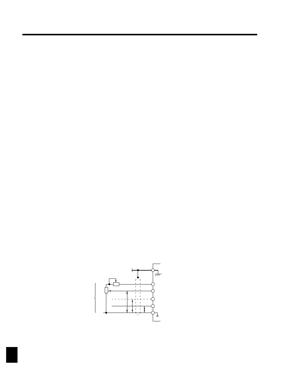
When setting frequencies from an external frequency setter (and not from a Digital Operator), used shielded
twisted-pair wires and ground the shield to terminal 12, as shown in the following diagram.
0 V
35
Multi-function analog input
0 to 10 V (20 k
Ω
)
42
Master speed reference
4 to 20 mA (250
Ω
)
39
Master speed reference
0 to 10 V (20 k
Ω
)
36
Speed setting power supply
+15 V 20 mA
34
Shield terminal
38
2k
Ω
3
2
1
0 to +10 V
P
4 to 20 mA
0 to +10 V
0 V
External
frequency
reference
2 k
Ω
P
P
12