2 pg speed control card terminal blocks, Pg-a2 (for v/f with pg feedback mode only), Pg-b2 (for flux vector control mode only) – Yaskawa G5HHP Drive User Manual
Page 55: Pg-d2 (for v/f with pg feedback mode only)
3.7 Installing and Wiring PG Speed Control Cards
3 - 15
3.7.2 PG Speed Control Card Terminal Blocks
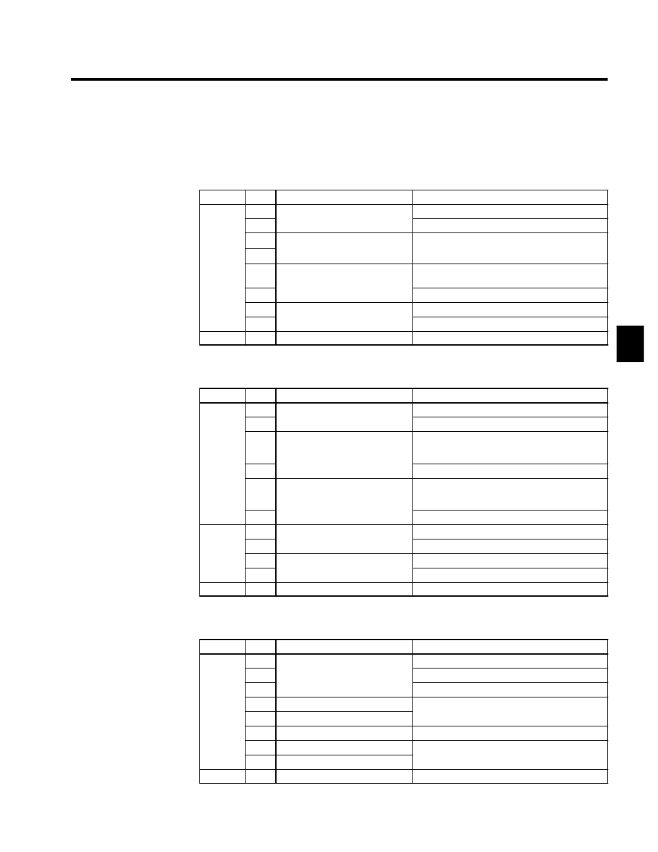
The terminal specifications for each PG Speed Control Card are given in the following tables.
J
PG-A2 (For V/f with PG Feedback Mode Only)
Table 3.3 PG-A2 Terminal Specifications
Terminal
No.
Contents
Specifications
1
Power supply for pulse generator
12 VDC (±5%), 200 mA max.
2
Power supply for pulse generator
0 VDC (GND for power supply)
3
+12 V/open collector switching ter-
Terminal for switching between12 V voltage input
and open collector input For open collector input
4
+12 V/open collector switching ter-
minal
and open collector input. For open collector input,
short across 3 and 4.
TA1
5
Pulse input terminal
H: +4 to 12 V; L: +1 V max. (Maximum response
frequency: 30 kHz)
6
Pulse input terminal
Pulse input common
7
Pulse motor output terminal
12 VDC (+10%), 20 mA max.
8
Pulse motor output terminal
Pulse monitor output common
TA2
(E)
Shield connection terminal
--
J
PG-B2 (For Flux Vector Control Mode Only)
Table 3.4 PG-B2 Terminal Specifications
Terminal
No.
Contents
Specifications
1
Power supply for pulse generator
12 VDC (±5%), 200 mA max.
2
Power supply for pulse generator
0 VDC (GND for power supply)
TA1
3
A-phase pulse input terminal
H: +8 to 12 V
L: +1 V max.
(Maximum response frequency: 30 kHz)
TA1
4
Pulse input common
5
B-phase pulse input terminal
H: +8 to 12 V
L: +1 V max.
(Maximum response frequency: 30 kHz)
6
Pulse input common
1
A phase monitor output terminal
Open collector output, 24 VDC, 30 mA max.
TA2
2
A-phase monitor output terminal
A-phase monitor output common
TA2
3
B phase monitor output terminal
Open collector output, 24 VDC, 30 mA max.
4
B-phase monitor output terminal
B-phase monitor output common
TA3
(E)
Shield connection terminal
--
J
PG-D2 (For V/f with PG Feedback Mode Only)
Table 3.5 PG-D2 Terminal Specifications
Terminal
No.
Contents
Specifications
1
12 VDC (±5%), 200 mA max. (see note)
2
Power supply for pulse generator
0 VDC (GND for power supply)
3
pp y
p
g
5 VDC (±5%), 200 mA max. (see note)
TA1
4
Pulse input + terminal
Line driver input (RS-422 level input)
TA1
5
Pulse input -- terminal
Line driver input (RS-422 level input)
Maximum response frequency: 300 kHz
6
Common terminal
--
7
Pulse monitor output + terminal
Line driver output (RS 422 level output)
8
Pulse monitor output -- terminal
Line driver output (RS-422 level output)
TA2
(E)
Shield connection terminal
--
3