Run source: b1-02, Operation after switching to remote mode: b1-07 – Yaskawa G5HHP Drive User Manual
Page 127
6.1 Common Settings
6 - 9
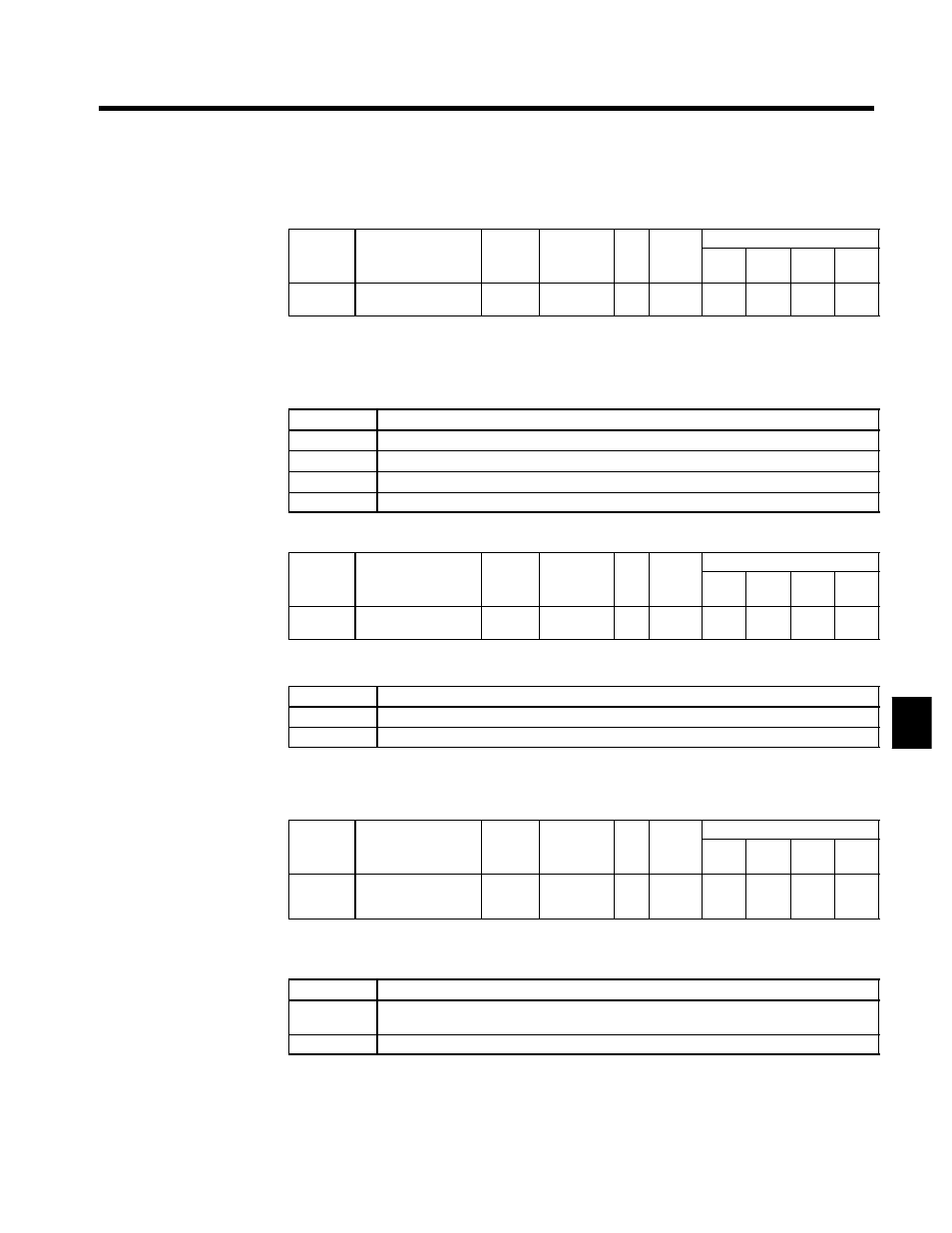
6.1.4 Run Source and Sequence Input Responsiveness: b1-02, b1-06, b1-07
J
Run Source: b1-02
User
Change
during
Setting
Factory
Valid Access Levels
User
Constant
Number
Name
g
during
Opera-
tion
Setting
Range
Unit Factory
Setting
V/f
Control
V/f with
PG
Open
Loop
Vector
Flux
Vector
b1-02
Operation method
selection
x
0 to 3
--
1
Q
Q
Q
Q
D
Constant b1-02 is used to select the source of the run command.
D
When a control circuit terminal (external terminal) is set, the Unit operates with 2-wire forward run/stop
and reverse run/stop control. (When the Unit has been initialized for a 3-wire control or a multi-function
input is set to 0 (3-wire sequence), the Unit operates with 3-wire run, stop and forward/reverse controls.)
D
Settings
Setting
Run source
0
Digital Operator
1
Control circuit terminals (external terminals)
2
Transmission
3
Optional Card
J
Sequence Input Responsiveness (Reading Twice): b1-06
User
Change
during
Setting
Factory
Valid Access Levels
User
Constant
Number
Name
g
during
Opera-
tion
Setting
Range
Unit Factory
Setting
V/f
Control
V/f with
PG
Open
Loop
Vector
Flux
Vector
b1-06
Read sequence input
twice
x
0, 1
--
1
A
A
A
A
D
Set the responsiveness of the control inputs (forward/reverse run and multi-function inputs)
D
Settings
Setting
Function
0
Two scans every 2 ms (Use when connecting transistor outputs.)
1
Two scans every 5 ms (Use when connecting contact outputs or switches.)
D
Set the responsiveness to match the type of control inputs being used. Use a setting of 1 if there is one
or more contact inputs.
J
Operation after Switching to Remote Mode: b1-07
User
Change
during
Setting
Factory
Valid Access Levels
User
Constant
Number
Name
g
during
Opera-
tion
Setting
Range
Unit Factory
Setting
V/f
Control
V/f with
PG
Open
Loop
Vector
Flux
Vector
b1-07
Operation selection
after switching to re-
mote mode
x
0, 1
--
0
A
A
A
A
D
Set the interlock operation to be used after switching from local mode (operation from Digital Operator)
to remote mode (operation according to control circuit terminal).
D
Settings
Setting
Function
0
No operation even if RUN signal is ON after switching to remote mode. (Operation will start if
the RUN signal turns OFF and then back ON after switching to remote mode.)
1
Operate according to the RUN signal after switching to remote mode.
6