Yaskawa G5HHP Drive User Manual
Page 155
6.4 Flux Vector Control
6 - 37
Adjusting ASR Proportional Gain 1 (C5-01)
D
This gain setting adjusts the responsiveness of the speed control (ASR).
D
The responsiveness is increased when this setting is increased. Usually this setting is higher for larger
loads. Oscillation will occur if this setting is increased too much.
D
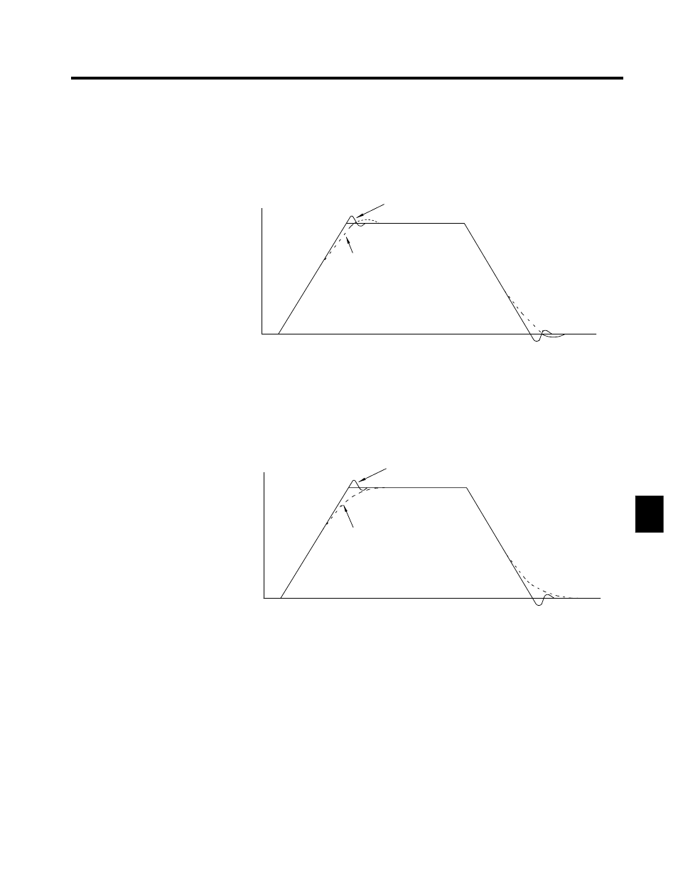
The following diagram shows the type of changes that can occur in the response when the ASR propor-
tional gain is changed.
The proportional gain is low.
The proportional gain is high.
(Oscillation occurs when the gain is too high.)
Motor speed
Time
Fig 6.19
Responsiveness for Proportional Gain
Adjusting ASR Integral Time 1 (C5-02)
D
This constant sets the speed control (ASR) integral time.
D
Lengthening the integral time lowers the responsiveness, and weakens the resistance to external in-
fluences. Oscillation will occur if this setting is too short.
D
The following diagram shows the type of changes that can occur in the response when the ASR integral
time is changed.
Motor speed
Time
Short integral time
Long integral time
Fig 6.20
Responsiveness for Integral Time
J
Different Gain Settings for Low-speed and High-speed
Switch between low-speed and high-speed gain when oscillation occurs because of resonance with the me-
chanical system at low speed or high speed.
Setting the Gain Switching Frequency (C5-07)
D
Set the switching frequency to about 80% of the motor operating frequency or the frequency at which
oscillation occurs.
Low-speed Gain Adjustments (C5-03, C5-04)
D
Connect the actual load and adjust these constants at zero-speed. Increase ASR proportional gain 2
(C5-03) until there is no oscillation.
D
Decrease ASR integral time 2 (C5-04) until there is no oscillation.
6