3 pg speed control card settings, Available pg speed control cards, Setting the pg pulse number: f1-01 – Yaskawa G5HHP Drive User Manual
Page 159
6.5 V/f Control with PG
6 - 41
6.5.3 PG Speed Control Card Settings
J
Available PG Speed Control Cards
D
There are 4 models of PG Speed Control Cards, but only 2 models can be used with vector control.
•
PG-A2: Phase-A/Phase-B pulse inputs, complementary output
•
PG-D2: Phase-A/Phase-B/Phase-Z pulse inputs, line drivers
D
Select the Card according to the application and install it in the Inverter as described in 3.7 Installing
and Wiring PG Speed Control Cards.
J
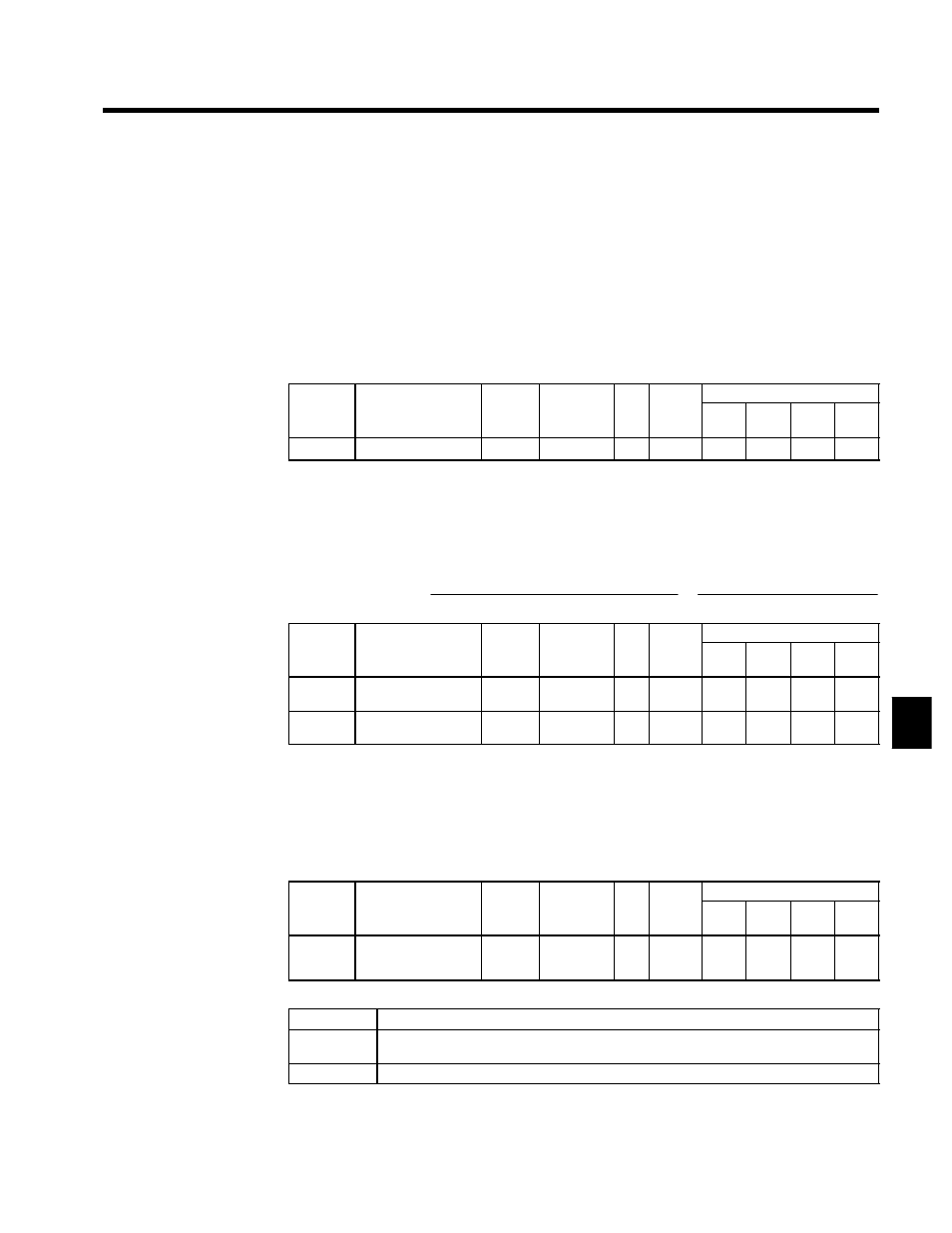
Setting the PG Pulse Number: F1-01
D
Set the PG (pulse generator or encoder) pulse number in pulses/revolution.
D
Set the number of phase A or phase B pulses in one motor revolution.
User
Change
during
Setting
Factory
Valid Access Levels
User
Constant
Number
Name
g
during
Opera-
tion
Setting
Range
Unit Factory
Setting
V/f
Control
V/f with
PG
Open
Loop
Vector
Flux
Vector
F1-01
PG constant
x
0 to 60000
p/r
600
x
Q
x
Q
J
Setting the Number of PG Gear Teeth: F1-12, F1-13
D
When “V/f control with PG feedback” is used, the motor can be operated even if there are gears between
the motor and PG because the responsiveness is lower than it is with vector control.
D
Set the number of teeth on the gears if there are gears between the motor and PG.
D
The motor speed will be calculated within the Inverter using the following equation:
Motor speed (r∕min) =
Number of pulses input from the PG × 60
Number of PG pulses (F1--01)
×
Number of gear teeth 2 (F1--13)
Number of gear teeth 1 (F1--12)
User
Change
during
Setting
Factory
Valid Access Levels
User
Constant
Number
Name
g
during
Opera-
tion
Setting
Range
Unit Factory
Setting
V/f
Control
V/f with
PG
Open
Loop
Vector
Flux
Vector
F1-12
Number of PG gear
teeth 1
x
0 to 1000
--
0
x
A
x
x
F1-13
Number of PG gear
teeth 2
x
0 to 1000
--
0
x
A
x
x
D
A gear ratio of 1 (F1-12 = F1-13 = 1) will be used if either of these constants is set to 0.
J
Selecting Integral Operation During Acceleration/Deceleration: F1-07
D
When “V/f control with PG feedback” is used, integral control during acceleration and deceleration can
be enabled or disabled with F1-07.
D
Set F1-07 to “1” (integral control enabled) if you want to keep the motor speed as close to the frequency
reference as possible during acceleration and deceleration. Set F1-07 to “0” (integral control disabled)
if you want to prevent the occurrence of overshooting/undershooting.
User
Change
during
Setting
Factory
Valid Access Levels
User
Constant
Number
Name
g
during
Opera-
tion
Setting
Range
Unit Factory
Setting
V/f
Control
V/f with
PG
Open
Loop
Vector
Flux
Vector
F1-07
Integral value during
accel/decel enable/dis-
able
x
0, 1
--
0
x
B
x
x
D
Settings
Setting
Function
0
Disabled (The integral function isn’t used while accelerating or decelerating; it is used at constant
speeds.)
1
Enabled (The integral function is used at all times.)
6