4 speed control (asr) structure, Gain settings – Yaskawa G5HHP Drive User Manual
Page 161
6.5 V/f Control with PG
6 - 43
D
Settings
Setting
Function
0
Deceleration to stop using deceleration time 1 (C1-02).
1
Coast to stop
2
Emergency stop using the emergency-stop time (C1-09).
3
Continue operation (Display “DEV” and continue control.)
D
F1-10 and F1-11 Settings
Constant F1-10 sets the PG speed deviation detection level as a percentage of the maximum output fre-
quency. Constant F1-11 sets the length of time in seconds that the difference between the motor speed
and reference speed must exceed the PG speed deviation detection level in order to detect a PG speed
deviation (DEV).
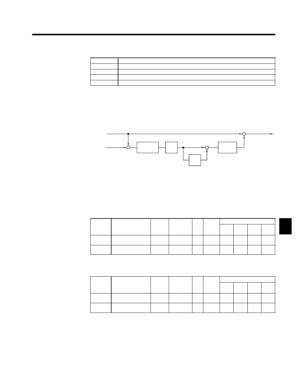
6.5.4 Speed Control (ASR) Structure
D
The following block diagram shows the structure of the speed control.
Change
limiter
Output fre-
quency
Frequency
reference
--
C5-01, C5-03
P
I
+
+
C5-02, C5-04
C5-05
Detected
speed
+
+
+
Limiter
Fig 6.21
Speed Control Structure
J
Gain Settings
D
When using “V/f control with PG feedback,” set the gain at the minimum output frequency and maxi-
mum output frequency.
Max. Output Frequency Gain Settings: C5-01 C5-02
D
Set the proportional gain (C5-01) and the integral time (C5-02) of the speed control (ASR).
User
Change
during
Setting
Factory
Valid Access Levels
User
Constant
Number
Name
g
during
Opera-
tion
Setting
Range
Unit Factory
Setting
V/f
Control
V/f with
PG
Open
Loop
Vector
Flux
Vector
C5-01
ASR proportional (P)
gain 1
f
0.00 to
300.00
Mul-
tiple
0.20
X
B
X
B
C5-02
ASR integral (I) time
1
f
0.000
to10.000
s
0.200
X
B
X
B
Min. Output Frequency Gain Settings: C5-03 C5-04
D
Set ASR proportional gain 2 (C5-03) and ASR integral time 2 (C5-04) for the minimum output frequen-
cy.
User
Change
during
Setting
Factory
Valid Access Levels
User
Constant
Number
Name
g
during
Opera-
tion
Setting
Range
Unit Factory
Setting
V/f
Control
V/f with
PG
Open
Loop
Vector
Flux
Vector
C5-03
ASR proportional (P)
gain 2
f
0.00 to
300.00
Mul-
tiple
0.02
X
B
X
B
C5-04
ASR integral (I) time
2
f
0.000 to
10.000
s
0.050
X
B
X
B
D
Figure 6.22 shows how the proportional gain and integral time are calculated from constants C5-01
through C5-04.
6