Other options setup: f2 through f9 – Yaskawa G5HHP Drive User Manual
Page 291
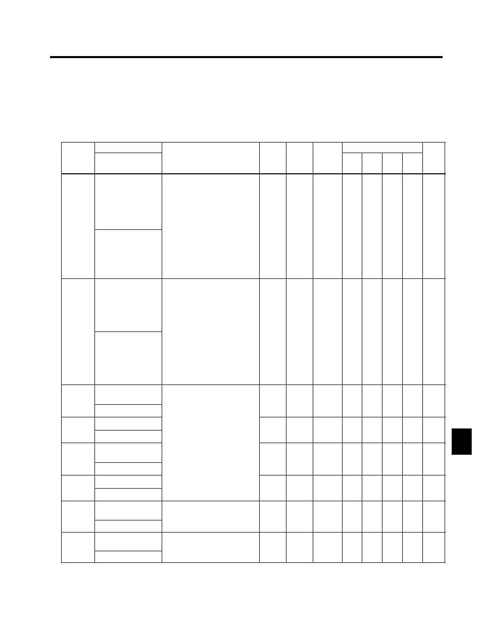
8.2 Programming Mode Constants
8 - 25
J
Other Options Setup: F2 through F9
F2: Analog Reference Card
F6: DO-08 Digital Output Card
F3: Digital Reference Card
F7: Pulse Monitor Card
F4: Analog Monitor Card
F8: SI-F/G
F5: DO-02 Digital Output Card
F9: DOS/SI-B
C
t t
Name
S tti
F t
Change
Control Methods
Constant
Number
Display
Description
Setting
Range
Factory
Setting
Change
during
Opera-
tion
V/f
V/f
with
PG
Open
Loop
Vector
Flux
Vector
Page
F2-01
Bi-polar or uni-polar
input selection
Sets the functions for channel 1 to 3
which are effective when the
AI-14B Analog Reference Card is
used.
0: 3-channel individual (Channel
1: terminal 13, Channel 2: ter-
minal 14, Channel 3: terminal
16)
0, 1
0
x
B
B
B
B
7 - 58
F2 01
AI-14 Input Sel
)
1: 3-channel addition (Addition
values are the frequency refer-
ence)
;
When set to 0, select 1 for b1-01.
In this case the multi-function in-
put “Option/Inverter selection”
cannot be used.
0, 1
0
x
B
B
B
B
7 - 58
F3-01
Digital input option
Sets the Digital Reference Card in-
put method.
0: BCD 1% unit
1: BCD 0.1% unit
2: BCD 0.01% unit
3: BCD 1 Hz unit
4 BCD 0 1 H
it
0 to 7
0
x
B
B
B
B
7 58
F3-01
DI Input
4: BCD 0.1 Hz unit
5: BCD 0.01 Hz unit
6: BCD special setting (5-digit in-
put)
7: Binary input
;
6 is only effective when the
DI-16H2 is used.
0 to 7
0
x
B
B
B
B
7 - 58
F4-01
Channel 1 monitor
selection
Effective when the Analog Monitor
Card is used.
Monitor selection:
1 to 33
2
x
B
B
B
B
7 - 59
F4 01
AO Ch1 Select
Monitor selection:
Set the number of the monitor
item to be output (U1-
)
1 to 33
2
x
B
B
B
B
7 - 59
F4-02
Channel 1 gain
item to be output. (U1-
)
Gain:
S t th
lti l
f 10 V f
t
0.00 to
1 00
f
B
B
B
B
7 59
F4-02
AO Ch1 Gain
Set the multiple of 10 V for out-
putting monitor items.
0.00 to
2.50
1.00
f
B
B
B
B
7 - 59
F4-03
Channel 2 monitor
selection
p
g
;
4, 10, 11, 12, 13, 14, 25, 28 can-
not be set. 29 to 31 are not used.
When the AO-12 is used outputs
f 10
ibl
hi
1 to 33
3
x
B
B
B
B
7 - 59
F4 03
AO Ch2 Select
When the AO 12 is used outputs
of ± 10 V are possible. In this
case, set H4-07 (select multi-
f
i
l
i
l
1 to 33
3
x
B
B
B
B
7 - 59
F4-04
Channel 2 gain
case, set H4 07 (select multi
function analog output signal
level) to 1. When the AO-08 is
d
l
t t f 0 t
10 V
0.00 to
0 50
f
B
B
B
B
7 59
F4-04
AO Ch2 Gain
eve ) to . W e t e O 08 s
used, only outputs of 0 to +10 V
are possible.
0.00 to
2.50
0.50
f
B
B
B
B
7 - 59
F5-01
Channel 1 output
selection
Effective when a Digital Output
Card is used.
S t th n mb r of th m lti f nc
0.0 to
37
0
x
B
B
B
B
7 - 59
F5 01
DO-02 Ch1 Select
Set the number of the multi-func-
tion output to be output.
37
0
x
B
B
B
B
7 - 59
F5-02
Channel 2 output
selection
Effective when a Digital Output
Card is used.
S t th n mb r of th m lti f nc
0.0 to
37
1
x
B
B
B
B
7 - 59
F5 02
DO-02 Ch2 Select
Set the number of the multi-func-
tion output to be output.
37
1
x
B
B
B
B
7 - 59
8