Yaskawa G5HHP Drive User Manual
Page 223
7.5 Common Functions
7 - 59
J
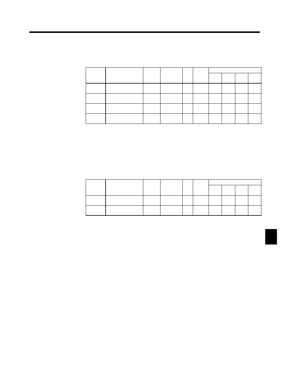
Analog Monitor Card: F4-01 to F4-04
D
When using an AO-08 or AO-12 Analog Monitor Card, set the monitor items and gain with the follow-
ing constants.
User
Change
during
Setting
Factory
Valid Access Levels
User
Constant
Number
Name
g
during
Opera-
tion
Setting
Range
Unit Factory
Setting
V/f
Control
V/f with
PG
Open
Loop
Vector
Flux
Vector
F4-01
Channel 1 monitor
selection
x
1 to 35
--
2
B
B
B
B
F4-02
Channel 1 gain
f
0.00 to 2.50 Mul-
tiple
1.00
B
B
B
B
F4-03
Channel 2 monitor
selection
x
1 to 35
--
3
B
B
B
B
F4-04
Channel 2 gain
f
0.00 to 2.50 Mul-
tiple
0.50
B
B
B
B
D
For the output monitor selections (F4-01, F4-03), set the numbers for the right side of the “U1” constants
in the Table 4.3. The setting range is 1 to 35, but the following numbers cannot be set: 4, 10, 11, 12, 13,
14, 25, and 28 to 35.
D
When the AO-12 is used, outputs of 0 to ±10 V are possible. For that, set constant H4-07 (multi-function
analog output signal level selection) to “1” (0 to ±10 V outputs). There are some monitor items.
However, that can only use outputs of 0 to +10 V even if constant H4-07 is set to “1.”
D
When the AO-08 is used, only outputs of 0 to +10 V are possible regardless of the constant H4-07 set-
ting.
J
DO-02 Digital Output Card Settings: F5-01, F5-02
D
Set the output selections in the following constants when using a DO-02 Digital Output Card.
User
Change
during
Setting
Factory
Valid Access Levels
User
Constant
Number
Name
g
during
Opera-
tion
Setting
Range
Unit Factory
Setting
V/f
Control
V/f with
PG
Open
Loop
Vector
Flux
Vector
F5-01
Channel 1 output
selection
x
00 to 37
--
0
B
B
B
B
F5-02
Channel 2 output
selection
x
00 to 37
--
1
B
B
B
B
D
Set the values from Table 7.10.
7