Trim control level: d4-02 – Yaskawa G5HHP Drive User Manual
Page 219
7.5 Common Functions
7 - 55
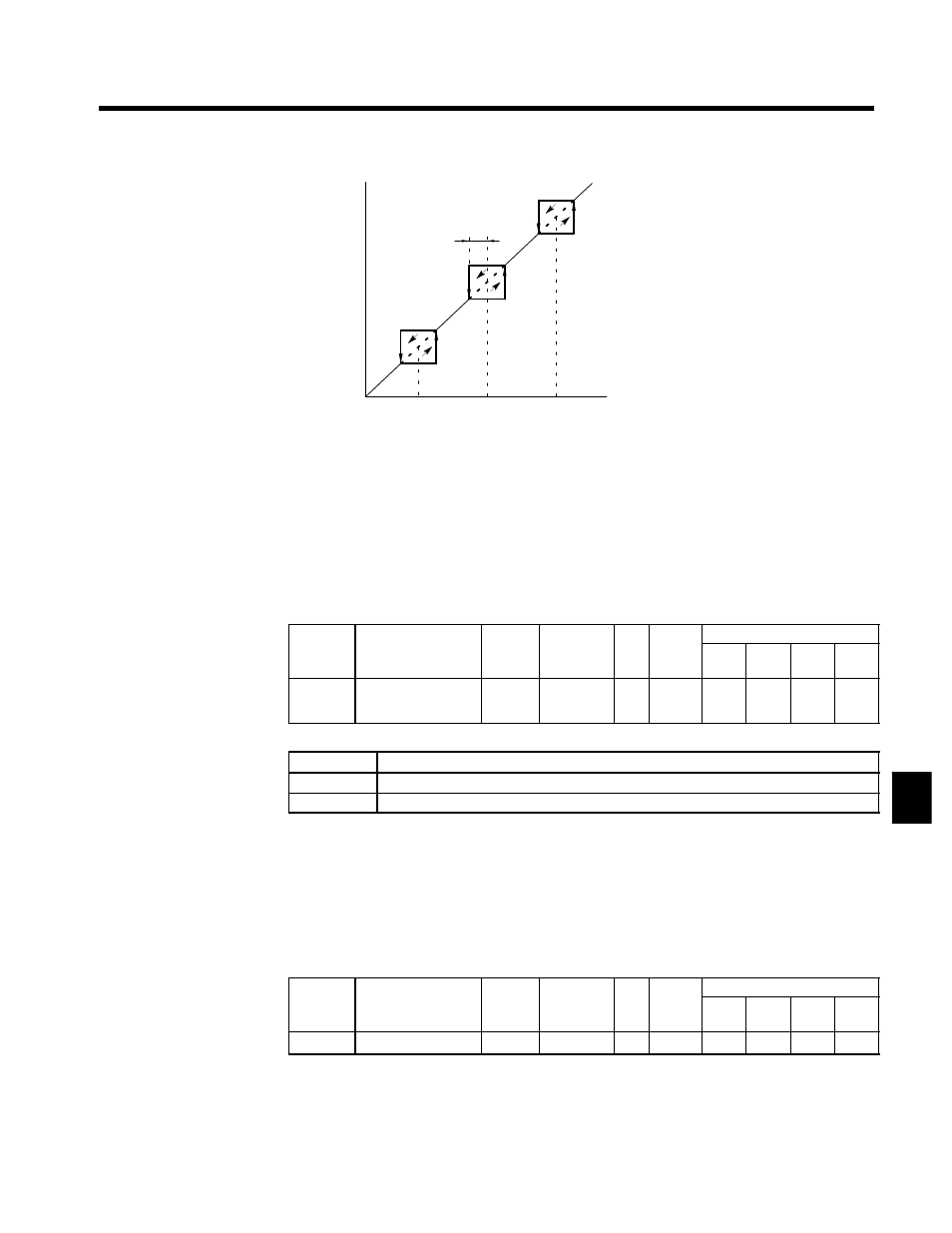
d3-04
d3-03
d3-02
d3-01
Internal frequency reference
Set frequency reference
Dotted lines show operation during
acceleration/deceleration.
Fig 7.28
Setting Prohibited Frequencies
J
Hold Reference Memory Selection: d4-01
D
Constant d4-01 is enabled by making either of the following settings for the multi-function inputs
(H1-01 to H1-06).
•
Acceleration/deceleration ramp hold (setting: A)
•
Up command (setting: 10)/down command (setting: 11)
D
When hold status is established by these external signals, specify whether or not the output frequency
is to be retained.
D
When this function is enabled, operation is re-started after power-up using the frequency reference value
that was retained.
User
Change
during
Setting
Factory
Valid Access Levels
User
Constant
Number
Name
g
during
Opera-
tion
Setting
Range
Unit Factory
Setting
V/f
Control
V/f with
PG
Open
Loop
Vector
Flux
Vector
d4-01
Frequency reference
hold function selec-
tion
x
0, 1
--
0
A
A
A
A
D
Settings
Setting
Description
0
Disabled. Restart after operation stoppage or power-up begins at zero.
1
Enabled. Restart after operation stoppage or power-up begins at the held frequency reference.
D
For information regarding the acceleration/deceleration stop (hold) command and the up/down com-
mand, refer to the description of Multi-function Inputs (H1).
J
Trim Control Level: d4-02
D
The trim control level is valid when the trim control increase command (setting: 1C) or trim control de-
crease command (setting: 1D) is set for a multi-function input (H1-01 to H1-06).
D
If the trim control increase command is ON when a frequency reference is input on the analog input,
the trim control level will be added to the analog frequency reference and then output as the output fre-
quency. If the trim control decrease command is ON, the frequency reference will be decreased by the
trim control level.
User
Change
during
Setting
Factory
Valid Access Levels
User
Constant
Number
Name
g
during
Opera-
tion
Setting
Range
Unit Factory
Setting
V/f
Control
V/f with
PG
Open
Loop
Vector
Flux
Vector
d4-02
+ -- Speed limits
x
0 to 100
%
25
A
A
A
A
D
Set the trim control level as a percentage of the maximum output frequency.
D
If the frequency reference minus the trim control level is less than zero, the output frequency will be
zero.
D
Refer to the description of Multi-function Inputs (H1) for details on the trim control increase and trim
control decrease commands.
7