Yaskawa G5HHP Drive User Manual
Page 245
7.5 Common Functions
7 - 81
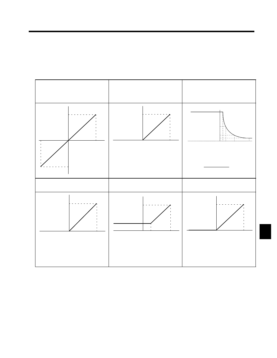
Analog Input Characteristics
D
Analog input characteristics for a gain of 100.0% and a bias of 0.0% are shown for setting examples in
Table 7.12.
D
To set over 100% for a 10 V input (e.g., 300%/10 V), set the gain to 300% in H3-06 for terminal 42 and
H3-10 for terminal 39.
Table 7.12 Analog Input Characteristics
S
Auxiliary Frequency Reference (Setting: 0)
S
Frequency Bias (Setting: 2)
S
PID Feedback (Setting: B)
S
Frequency reference (H3-09 setting: 1F)
S
Frequency Gain (Setting: 1)
S
Output Voltage Bias (Setting: 4)
S
DC Injection Braking Current (Setting: 6)
S
Acceleration/Deceleration Time Gain (Set-
ting: 5)
--10 V
0
10 V
100 %
--100 %
When set to “1,” the setting of H3-02 will be
added to achieve the final gain.
--10 V
0
10 V
100 %
--10 V
0
10 V
100 %
10 %
50 %
20 %
5 V
1V 2V
Acceleration/deceleration time gain between
1 and 10 V.
=
10V
Input voltage (V) × 10(%)
S
DC Injection Braking Current (Setting: 6)
S
Overtorque Detection Level (Setting: 7)
S
Stall Prevention Level (Setting: 8)
S
Output Frequency Lower Limit (Setting: 9)
S
Jump Frequency (Setting: A)
Only the overtorque detection 1 output can be
used when “7” is set to use overtorque detec-
tion for a multi-function output.
--10 V
0
10 V
100 %
3 V
--10 V
0
10 V
100 %
30 %
--10 V
0
10 V
100 %
7