Multi program 2 mode settings (basic, Operation), Multi program 2 mode settings (basic operation) – Sony GP-X1EM Grip Extension User Manual
Page 203
203
• Setting the Multi Program 2 data to recall in keyframes
and snapshots
• Changing the key assignment for program output
• Assigning sub bank preview output to buttons
• Changing the matrix size to standard
• Making settings for keyframe timeline operation
Multi Program 2 Mode Settings
(Basic Operation)
Entering the software install key (first time
only)
After installing XZS-9200 (for XVS-9000), XZS-8200
(for XVS-8000), XZS-7200 (for XVS-7000), or
XZS-6200 (for XVS-6000) Multi Program 2 Software in
the switcher, carry out the following procedure.
1
In the status area of the Engineering Setup >System
>Install/Unit Config menu (7316), select SWR1 or
SWR2, and press [License].
The License menu (7316.6) appears.
2
Enter the software install key.
For details, see “Configuring Settings to Use the
Software” (page 402).
3
Turn the switcher off and then on again.
Setting the operating mode for a switcher
bank
Set Multi Program 2 mode for each switcher bank.
1
Open the Engineering Setup >Switcher >Config menu
(7331).
2
In the status area, select the target switcher bank.
3
In the <M/E Config> group, select [Multi Program2].
4
Repeat steps
2
and
3
as required, to set the operation
mode for all target switcher banks.
Assigning output signals for Multi
Program 2 mode
To assign a signal to an output
Use the Engineering Setup >Switcher >Config >M/E
Output Assign menu (7331.1).
In Multi Program 2 mode, you can assign signals in the
following configuration to six outputs (Out1 to Out6).
• Out1: Main program output (PGM1) (fixed)
• Out2: Main output signals assignable
• Out3, Out4: Main and sub output signals assignable
• Out5: Sub output signals assignable
• Out6: Sub program output (PGM2) (fixed)
For details, see “Assigning the output of each bank in
multi-program mode” (page 442).
When M/E split 2M/E mode is set on the XVS-9000, there
are four available outputs which can be assigned with
signals with the following configuration in Multi Program
2 mode.
• Out1: Main program output (PGM1) (fixed)
• Out2: Main output signals assignable
• Out3, Out4: Main and sub output signals assignable
By default, the Out6 output signal on each switcher bank
is assigned to the sub re-entry buttons on the cross-point
pad
. To use the sub re-entry buttons in
M/E split 2M/E mode, the video/key pair number
assignments must be changed to the sub program output
(PGM2) signal as shown below.
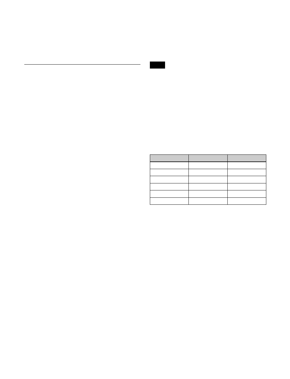
Example: When PGM2 is assigned to Out4
To set the background and key configuration
Use the Engineering Setup >Switcher >Config >PGM
Config menu (7331.2).
The differences from operation in standard mode are as
follows.
Background configuration:
Consists of the following
combinations.
• Main bank: Clean, Bkgd A, Bkgd B
• Sub bank: Sub Clean, Utility 2, Utility 3
Key configuration:
Key1 can be enabled only when the
background is Clean, Bkgd A, or Bkgd B.
For details, see “Setting the output configuration for each
bank” (page 442).
To set the key preview configuration
Use the Engineering Setup >Switcher >Config >K-PVW
Config menu (7331.3).
The differences from operation in standard mode are as
follows.
Background configuration:
Clean or Sub Clean
Key configuration:
Key1 can be set to [On] or [Link] only
when the background is Clean.
Note
V/K pair number
Video signal
Key signal
216
P/P OUT4
P/P OUT4
226
M/E-1 OUT4
M/E-1 OUT4
236
M/E-2 OUT4
M/E-2 OUT4
246
M/E-3 OUT4
M/E-3 OUT4
256
M/E-4 OUT4
M/E-4 OUT4
266
M/E-5 OUT4
M/E-5 OUT4