Sony GP-X1EM Grip Extension User Manual
Page 317
317
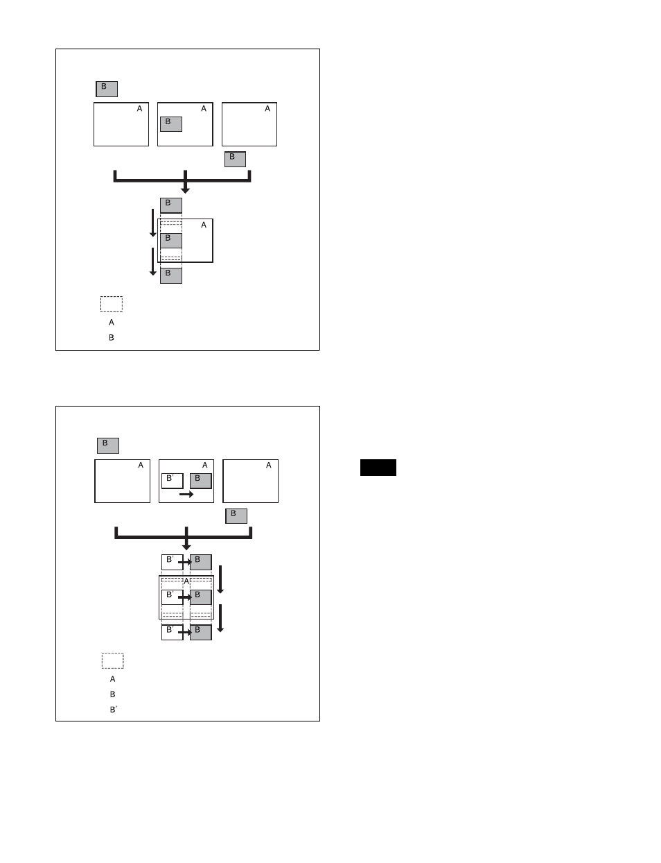
At the first transition completion point, if you move the
image with the positioner, the transition appears as
follows.
Signals forming part of the background for
a DME wipe
For a 2-channel mode page turn, roll, brick, frame in-out,
and so on, the part of the pattern image shown in gray is
filled with the signal selected on the DME external video
bus.
For 3-channel mode brick, the part of the pattern image
shown in dark gray is filled with the signal selected on the
DME external video bus, and the light gray portion is filled
with the signal selected on the DME utility 1 bus.
For details about patterns, see “DME Wipe Pattern List”
(page 498).
Setting the transition mode
1
Open the Key Frame >DME User PGM menu (6114).
2
In the <Transition Mode> group, select the transition
mode according to the DME wipe action.
Single:
Select single transition mode.
Flip Tumble:
Select flip tumble transition mode.
Dual:
Select dual transition mode.
P in P:
Select picture-in-picture transition mode.
Compress:
Select compress transition mode.
Frame I/O:
Select frame in-out transition mode.
Frame I/O H:
Select frame in-out transition mode in
the horizontal direction.
Frame I/O V:
Select frame in-out transition mode in
the vertical direction.
For details about user programmable DME, see
“Creating User Programmable DME Patterns”
(page 168).
The DME channel selected as the reference region (lit
green) in the numeric keypad control block is reflected
in the <Transition Mode> group display.
Transition
start
Transition
end
First transition
completion
point
Image created by interpolation
Background A
Background B
Effect execution
Image created by interpolation
Background A
Background B
Effect execution
State before modification
Transition
start
Transition
end
First transition
completion
point
Note