Split fader – Sony GP-X1EM Grip Extension User Manual
Page 98
98
an auto transition, which can always be executed
regardless of the fader lever direction.
• When a transition uses a combination of more than one
of the background and key 1 to key 8, then the transition
for all of these must be in the same direction complying
with the above table.
• If as a result of an auto transition, for example, the fader
lever position does not agree with the signal output of
each bus, a non-sync state
results and
LEDs light/flash at both end positions of the fader lever
travel.
Split Fader
Split fader is a function that splits a single fader lever into
left and right, allowing you to control background A bus
and background B bus transitions independently.
The fader lever on the transition control block (simple
type) is split into two by pressing the lock button to unlock
the two fader levers for use as split faders.
The split fader levers support the following buses. You can
change the settings in the Setup menu.
• Right fader lever: Background A bus (main)
• Left fader lever: Background B bus
The following conditions must be satisfied in order to use
the fader lever as split faders.
• Bus fixed mode is set.
• Split faders are enabled.
• Mix or NAM (non-additive mix) is selected for
transition type.
• If the transition type is a clip transition, Mix or NAM
(non-additive mix) is selected for the background
transition type.
If these conditions are not satisfied, only the main
(background A bus) fader lever can be operated.
For details about split fader settings, see “Setting the Main
Fader Lever” (page 430) and “Enabling/disabling split
faders” (page 470).
When not using split fader lever operation, disable split
faders.
If enabled, a black image or super mix image may be
output when the transition type is changed.
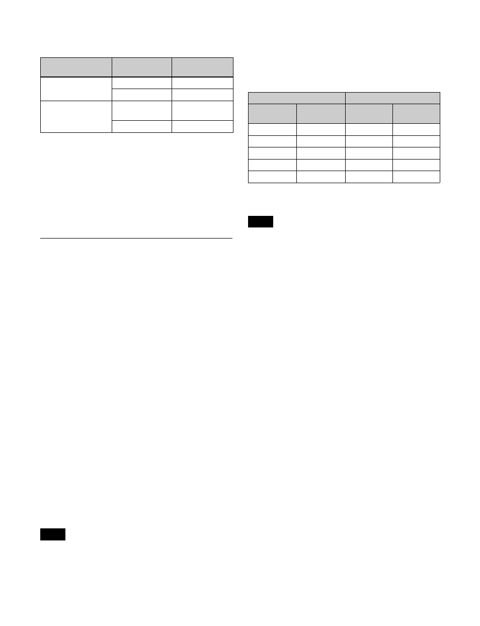
Split fader operation
The relationship between the position of the fader lever
and the output for a mix transition type is given below.
The A bus and B bus output for a NAM transition type is
an image created using non-additive mixing.
The transition indicator displays the progress of the
background A bus.
Next transition
Transition
direction
Fader lever
movement
Background
A
t
B
Top
t
Bottom
B
t
A
Bottom
t
Top
Key 1 to key 8
On
t
Off
(remove)
Top
t
Bottom
Off
t
On (insert) Bottom
t
Top
Note
Fader lever position
Output
Right lever
(A bus)
Left lever
(B bus)
A bus
B bus
Top
Top
100%
0%
Top
Bottom
100%
100%
Bottom
Top
0%
0%
Bottom
Bottom
0%
100%
Center
Center
50%
50%
Note