Corner pinning settings – Sony GP-X1EM Grip Extension User Manual
Page 276

276
Field:
Do interpolation in field units. This gives
natural movement, suitable for movies.
Frame:
Do interpolation in frame units. This gives
higher image precision, suitable for still pictures.
5
When [Adaptive] is selected in step
4
, set the
following parameter.
6
In the <Interpolation Mode> group, set the number of
pixels to use in interpolation.
Multi:
Use multi-point interpolation. This gives
higher picture quality.
Linear:
Use two-point interpolation.
7
In the <Filter Mode> group, select the method used to
control picture reduction or expansion.
Mode1:
Even when the picture is reduced, add
compensation so that it can be seen clearly
(standard).
Mode2:
Suppress aliasing when expanding or
reducing the picture (soft).
Mode3:
Do not suppress aliasing when expanding or
reducing the picture (sharp).
Corner Pinning Settings
When the Brick function is enabled, Corner Pinning
cannot be used.
Setting the foreground corner
1
Open the DME >Non Linear/Corner Pin >Corner
Pinning menu (4142).
2
Press [Corner Pinning], turning it on.
3
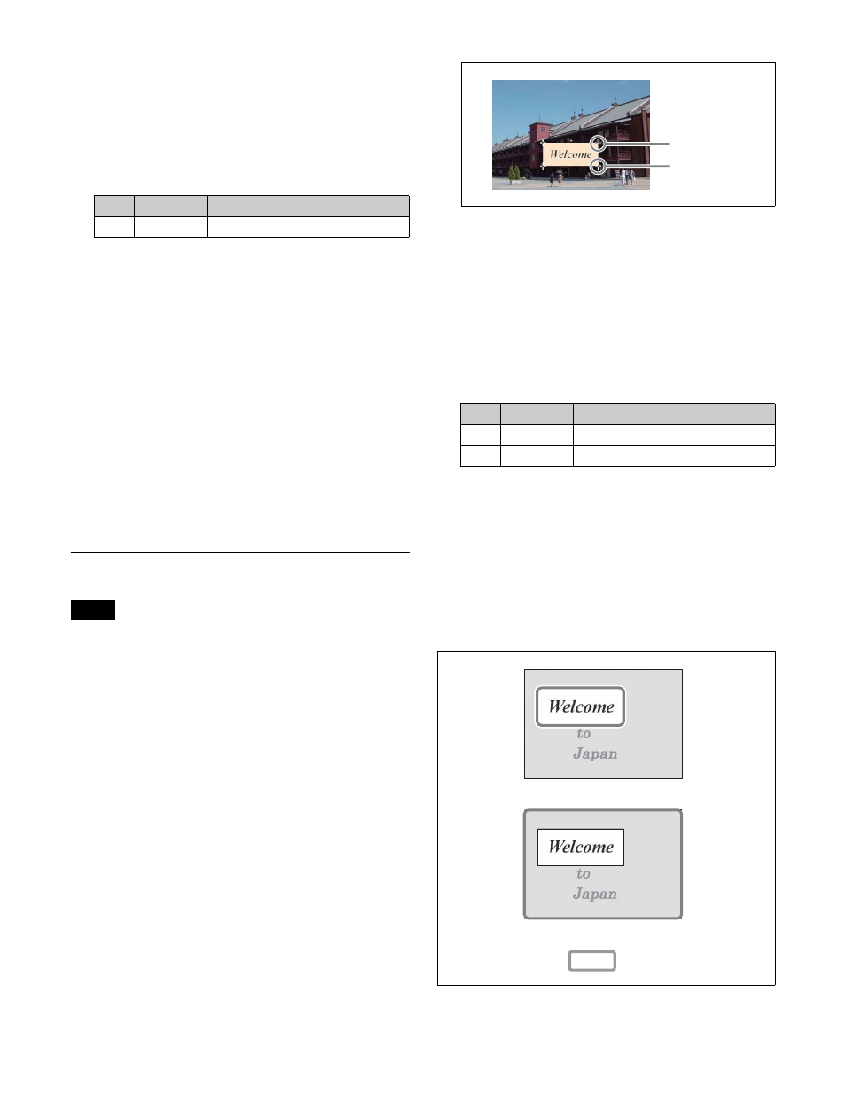
Press [Corner Marker], turning it on.
A marker appears for each corner. The marker for the
selected corner is distinguished from the other
markers.
4
In the <Corner Select> group, select the target corner
to set.
Top Left:
Top left corner
Top Right:
Top right corner
Bottom Left:
Bottom left corner
Bottom Right:
Bottom right corner
All:
All four corners
5
Set the position of the corner selected in step
4
.
To reset the corner positions
In the Corner Pinning menu (4142), press [Reset Corner].
To select the target area of the foreground
When the foreground is cropped, select the target range.
In the Corner Pinning menu (4142), press [Crop Link],
turning it on, to set the cropped image as the target range.
When [Crop Link] is disabled, the whole picture, including
the invisible cropped portions (gray portions in the
following diagram), become the target range.
No.
Parameter
Adjustment
1
Mode
Degree of change detection
Note
No.
Parameter
Adjustment
1
Pos X
Movement in X-axis direction
2
Pos Y
Movement in Y-axis direction
Active marker
Other markers
Target range with Crop Link disabled
Target range with Crop Link enabled
(
indicates the target range)