Sony GP-X1EM Grip Extension User Manual
Page 482
482
3
Press [Port Setting].
The P-Bus Setting menu (7355.1) appears.
The slot number/port number, device type, port name,
control panel number, and IP address and port number
of the network port appear at the top of the status area.
The device name and response speed settings status for
each command appear at the bottom of the status area.
4
For network ports, set the IP address and port number.
To set the IP address
Press [IP Address]. Enter the address using the
keyboard window, then press [Enter].
To set the port number
Press [Port]. Enter the port number using the numeric
keypad window, then press [Enter].
5
Select the target device ID to set.
6
To set the device name, press [Set] in the <Name>
group.
Enter the name using the keyboard window, and press
[Enter].
To return the device name to the default name
In the <Name> group, press [Clear].
7
Select the target command to set.
8
Set the response speed.
9
Press [Delay Set].
10
Repeat steps
7
to
9
as required to set other commands.
To set other device IDs, repeat from step
5
.
Configuring detailed settings for a VTR
1
In the <DCU Select> group of the Engineering Setup
>DCU >Serial/Net Port Assign menu (7355), select
the target to set (DCU1 or DCU2).
2
Select the port connected to the target VTR to set.
3
Press [Port Setting].
The VTR Setting menu (7355.2) appears.
The slot number/port number, device type, port name,
control panel number, and timecode source appear at
the top of the status area. The setting status of each
item appears at the bottom of the status area.
4
In the <TC Source> group, select the timecode source
(reference signal for determining the tape position).
LTC:
Use LTC (Longitudinal Time Code). When
interpolation data is returned from a VTR, use that
interpolation data.
LTC:VITC:
Normally use LTC, except when the tape
is moving at speeds at which LTC cannot be read,
use VITC (Vertical Interval Time Code). When
interpolation data is returned from a VTR, use that
interpolation data.
VITC:
Use VITC (Vertical Interval Time Code).
CTL:
Use CTL (Control) pulse or timer counter pulse.
Use this only for a tape on which no timecode is
recorded.
The displayed tape position is based on the specified
reference signal.
5
Select the target item to set.
6
Press [Set].
A numeric keypad window for hexadecimal input
appears.
7
Set the VTR constants using values in the range 00 to
FF.
8
Press [Enter].
9
Repeat steps
5
to
8
as required to make the settings for
other items.
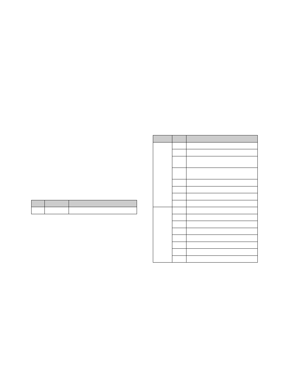
No.
Parameter
Adjustment
3
Delay
Response speed (number of fields)
Block
Byte
Item
1
1
HI-BYTE (DEVICE TYPE)
2
LO-BYTE (DEVICE TYPE)
3
HI-BYTE (FRAME) (PREROLL
TIME)
4
LO-BYTE (FRAME) (PREROLL
TIME)
5
EDIT DELAY (FRAME)
6
EE DELAY (FRAME)
7
OVER RUN (FRAME)
8
TRAJECTORY
2
1
TC READ DELAY (FRAME)
2
START DELAY (FRAME)
3
AFTER SYNC DELAY –
4
AFTER SYNC DELAY +
5
MODE1
6
MODE2
7
MAX PRRL SPEED
8
QUICK PVW PRRL TIME (FRAME)