Through mode, Adjusting video clips – Sony GP-X1EM Grip Extension User Manual
Page 459
459
Assigning a format converter output
You can assign format converter outputs 1 to 16 to format
converter output connectors 1 to 16 or spare connectors 1
to 4.
You can also assign frame memory outputs 1 to 20.
• Frame memory outputs 1 to 20 cannot be assigned when
the switcher signal format is 3840×2160P,
3840×2160PsF, or 1080P.
• On the XVS-7000, format converter outputs 9 to 16 are
assigned to format converter output connectors 9 to 16.
It is not possible to change settings.
• On the XVS-8000, format converter output connectors
and spare connectors connected to dedicated inputs
cannot be used
• The following functions are not supported on outputs
assigned to format converter output connectors and
spare connectors.
Video clips, vertical blanking, through mode, safe titles,
4:3 crop, AUX bus color corrector, AUX mix transitions
• When using a network connector board (XKS-T8165/
XKS-Q8166/XKS-C8166), outputs with the same signal
format must be assigned to each connector within the
following groups of four connectors. The signal format
of the output assigned to the first number connector is
applied to the four connectors. To output as a 4K format
signal, assign sub images 1 to 4 to the four connectors in
that order.
- Format converter output connectors 1 to 4, 5 to 8, 9 to
12, 13 to 16
- Spare connectors 1 to 4
1
In the Engineering Setup >Switcher >Output menu
(7333), press [FC Output Assign].
The FC Output Assign menu (7333.18) appears.
The status area shows a list of output connector
numbers and source names of assigned signals on the
left. The right side of the status area shows a list of
assignable signals.
2
Select the output connector number and signal to
assign.
For signals not assigned, select “Undefined” in the
signal list.
3
Press [Set].
Adjusting Video Clips
1
In the Engineering Setup >Switcher >Output menu
(7333), press [Video Clip].
The Video Clip menu (7333.2) appears.
2
Select the target output to set.
3
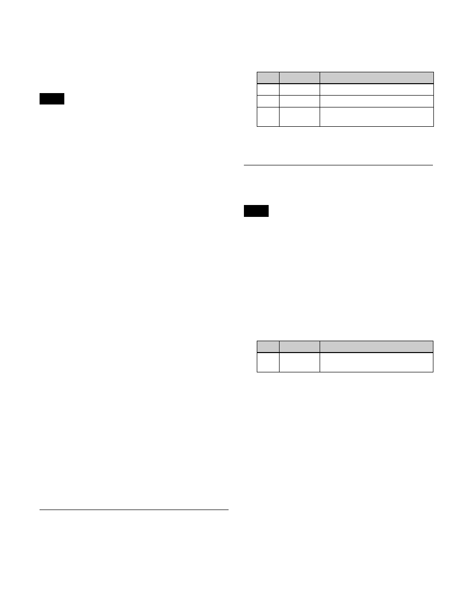
Set the following parameters.
To return the parameters to their default settings
Press [Default].
Setting the Vertical Blanking Interval
and Through Mode
Through mode cannot be set for outputs whose signal
format is converted by an output format converter.
1
In the Engineering Setup >Switcher >Output menu
(7333), press [V Blank/Through].
The V Blank/Through menu (7333.3) appears.
2
Select the target output to set.
3
Press [V Blank Mask], and set the following
parameter.
a) The adjustment range varies as follows, depending on the signal
format.
3840×2160P (also includes output when active area is set to
4096×2160), 1080P: 15 to 41
3840×2160PsF, 1080PsF, 1080i: 7 to 20
720P: 7 to 25
To return the parameters to their default settings
Press [Default].
4
To enable through mode, press [Through Mode],
turning it on.
Through mode can be enabled for the following
outputs.
• AUX1 to 48, Edit preview output
• Program outputs of each M/E and PGM/PST bank
• Clean outputs of each M/E and PGM/PST bank
Notes
No.
Parameter
Adjustment
2
White Clip
Luminance signal white clip value
3
Dark Clip
Luminance signal dark clip value
4
Chroma
Clip
Chrominance signal clip value
Note
No.
Parameter
Adjustment
2
Mask End
Final value for vertical blanking
interval
a)