Sony GP-X1EM Grip Extension User Manual
Page 25
25
Inhibiting operation of a cross-point button row
(protect function)
To inhibit operation of buttons on the 1st to 4th rows, press
the [ROW-1 PROT] to [ROW-4 PROT] buttons on the
cross-point pad, turning them on.
Inhibiting operation of a cross-point button row
(inhibit function)
To inhibit operation of a cross-point button, press and hold
the [XPT INHBT SET] button on the cross-point pad, and
press the target cross-point button you want to inhibit. To
release the inhibit setting, press and hold the [XPT INHBT
SET] button on the cross-point pad, and press the target
cross-point button you want to release.
To release the inhibit setting for all buttons, press and hold
the [XPT INHBT SET] button on the cross-point pad, and
press the [XPT INHBT ALLCLR] button.
For details about the inhibit function, see “Inhibiting
Operation of Cross-point Buttons” (page 82).
KEY button
In free assign mode or key/AUX bus delegation mode, you
can select the key signal of a V/K pair using the [KEY]
button on the cross-point pad.
When a cross-point button is pressed while pressing the
[KEY] button, the key signal is selected. When a cross-
point button is pressed without pressing the [KEY] button,
the video signal is selected.
When a key source signal is selected and an operation
mode that allows you to select both a key signal and video
signal is set in the Setup menu, the [KEY] button is
enabled. In key source signal operations, when the [KEY]
button is pressed, turning it on, and a cross-point button is
pressed, the key signal is selected. When the [KEY] button
is not lit and a cross-point button is pressed, the video
signal is selected.
Information for the key signal or video signal, whichever
is selected, appears on the display.
For details, see “Setting the Button and Fader Lever
Operation Mode” (page 432).
The [KEY] button cannot be used on the following buses.
Only the video signal is selectable.
• Key fill bus
• DME video bus
• Background A bus, B bus
b
Display
Six types of display mode can be selected, according to the
information to display. The display mode is switched using
the display mode buttons on the cross-point pad.
The following information can be shown on the display.
• Settings of buttons on the 1st row to 4th row (signal
name, bus name, register name, or function name
assigned to the button)
• Macro register name of macro attachment assigned to
the 1st to 4th row buttons
• When the [SHIFT] button function is set, “SHFT”
appears on the display. When the shifted state is selected,
“SHFT” is highlighted in reverse video, and the button
information also toggles to show the shifted display.
• When the [SIDE FLAG] button function is set, “SIDE
FLAG” appears on the display.
The information shown in each display mode is configured
in the Setup menu. The display can also be subdivided (top
and bottom) to display two pieces of information.
For details, see “Setting the Display Mode of the Cross-
Point Control Block/AUX Bus Control Block” (page 438).
c
Cross-point indicators
When lit, this indicates the source color of the video signal
assigned to buttons on the 3rd row.
If a signal cannot be selected, because a signal is not
assigned or the inhibit setting is set, the indicator is not lit.
You can set whether to enable the cross-point indicator in
the Setup menu.
For details, see “Setting cross-point indicators”
(page 435).
d
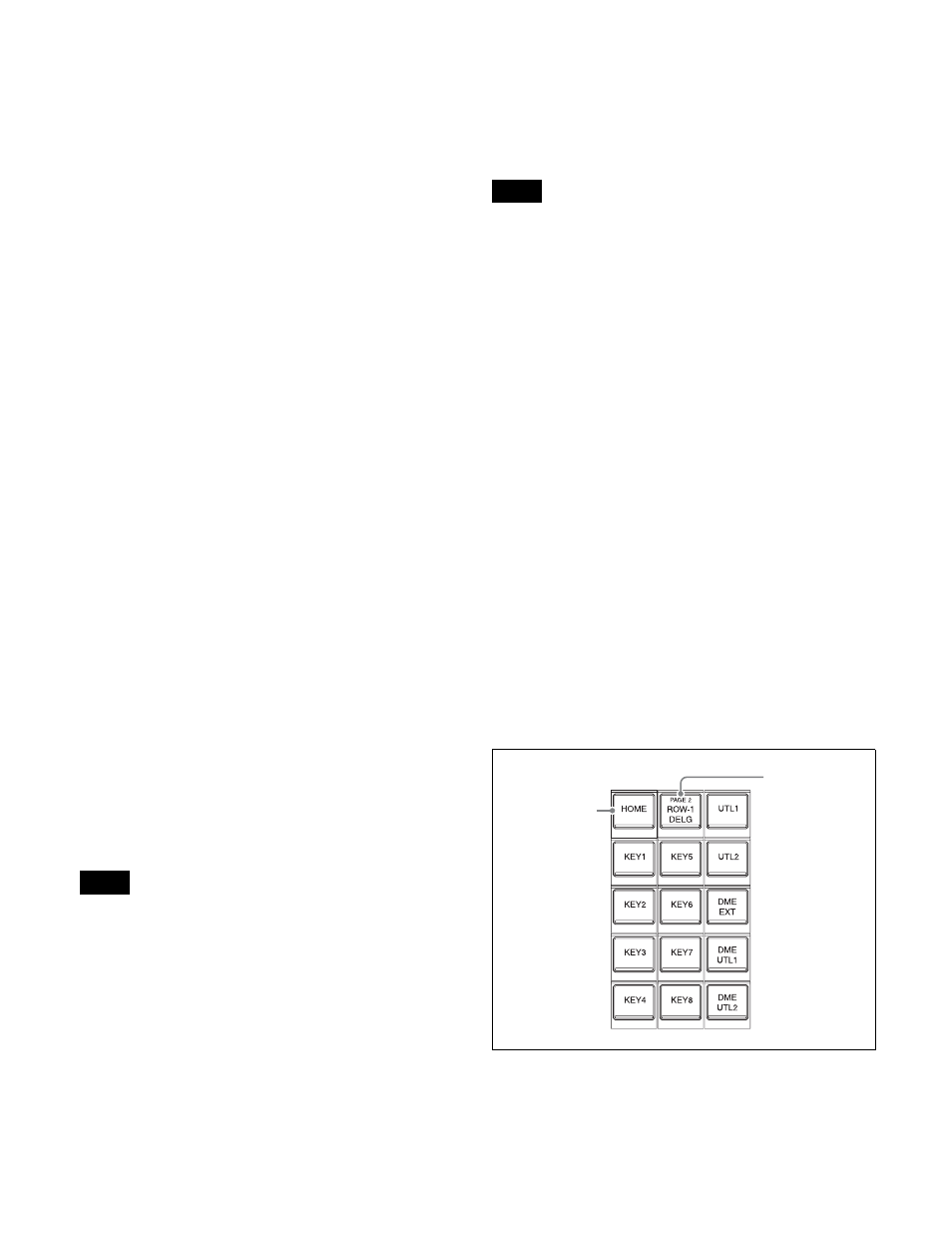
Cross-point pad
Contains button assignments for functions used for cross-
point operations, status display, and so on.
You can assign functions to each button in the Setup menu.
You can set up 14 pages of settings and assign an arbitrary
name to each M/E and PGM/PST bank.
Note
Notes
Current page
name indicator
button
HOME button