Input /p-con 1cn-41 – Yaskawa SGDB User Manual
Page 104
APPLICATIONS OF Σ-SERIES PRODUCTS
3.2.7 Using Torque Control
92
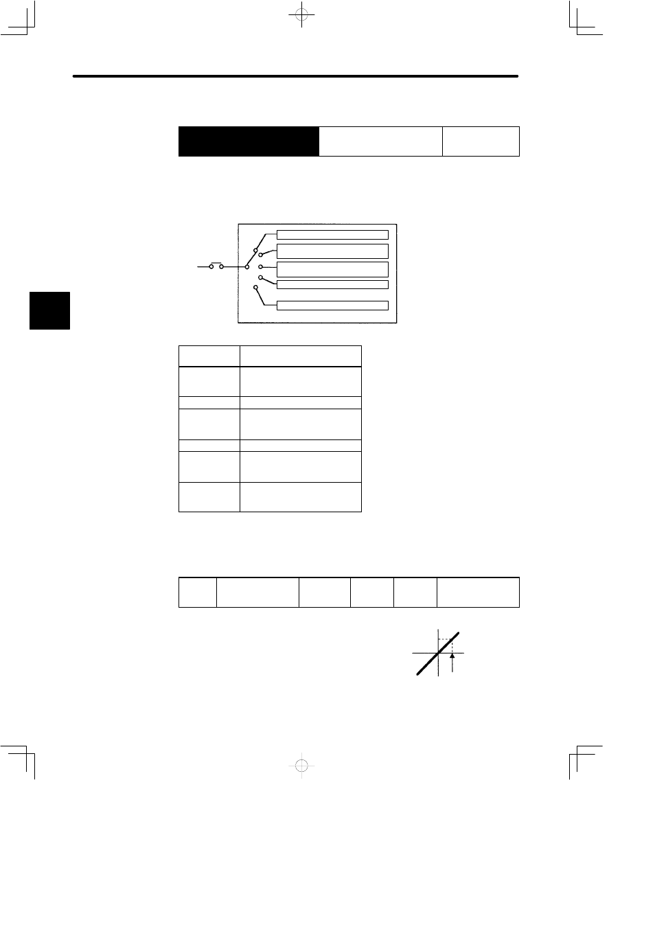
• Using /P-CON Signal
→ Input /P-CON
1CN-41
Proportional Control, etc.
For Speed/Torque
Control and
Position Control
• The function of this input signal varies according
to the Cn-2B setting.
SGDB SERVOPACK
Switching between zero-clamp enabled
mode and zero-clamp prohibited mode
Switching the control mode
Switching between INHIBIT enabled mode
and INHIBIT prohibited mode
Changing the direction of rotation
Switching between P control and PI control
/P-CON
Cn-2B
Cn-2B
Setting
Meaning of /P-CON Signal
0, 1
Switching between P control
and PI control.
2
(Not used)
3, 4, 5, 6
Switching the direction of
rotation when contact input
speed control mode is selected.
7, 8, 9
Switching the control mode.
10
Switching between zero-clamp
enabled and zero-clamp
prohibited modes.
11
Switching between INHIBIT
enabled and INHIBIT prohibited
modes.
J
Parameters
Set the following parameters for torque control according to the servo system used.
Cn-13
TCRFGN
Torque Reference
Gain
Unit:
0.1 V/Rated
Torque
Setting
Range:
10 to 100
Factory
Setting:
30
For Speed/Torque
Control Only
Sets the voltage range of torque reference input
T-REF (1CN-9) according to the output form of the
host controller or external circuit.
The factory setting is 30, so the rated torque is 3 V
(30 x 0.1).
3
Reference torque
Rated torque
Reference
voltage (V)
Set this reference voltage.