Yaskawa SGDB User Manual
Page 312
USING THE DIGITAL OPERATOR
5.4.1 Servomotor Dimensional Drawings cont.
302
in mm (inches)
Type
SGMG
Flange dimensions
yp
SGMG-
LA
LB
LC
LE
LF1
LF2
LG
LH
LJ1
LJ2
LZ
55A2AAB 200
(7.87) 114.3
0
− 0.025
(4.50
0
− 0.0010
)
180
(7.09)
3.2
(0.13)
3
(0.12)
0.5
(0.0197)
18
(0.71)
230
(9.06)
76
(2.99)
62
(2.44)
13.5
(0.53)
75A2AAB 200
(7.87) 114.3
0
− 0.025
(4.50
0
− 0.0010
)
180
(7.09)
3.2
(0.13)
3
(0.12)
0.5
(0.0197)
18
(0.71)
230
(9.06)
76
(2.99)
62
(2.44)
13.5
(0.53)
1AA2AAB 235
(9.25)
200
0
− 0.046
(7.87
0
− 0.0018
)
220
(8.66)
4
(0.16)
4
(0.16)
−
18
(0.71)
270
(10.63)
62
(2.44)
−
13.5
(0.53)
1EA2AAB 235
(9.25)
200
0
− 0.046
(7.87
0
− 0.0018
)
220
(8.66)
4
(0.16)
4
(0.16)
−
20
(0.79)
270
(10.63)
85
(3.35)
−
13.5
(0.53)
in mm (inches)
Type
SGMG-
Shaft end dimensions
Approx.
mass
SGMG
S
S1
Q
mass
kg
(lb)
55A2AAB
42
0
− 0.016
(1.65
0
− 0.0006
)
45
(1.77)
110
(4.33)
35
(77.14)
75A2AAB
42
0
− 0.016
(1.65
0
− 0.0006
)
45
(1.77)
110
(4.33)
45.5
(100.28)
1AA2AAB
42
0
− 0.016
(1.65
0
− 0.0006
)
45
(1.77)
110
(4.33)
65
(143.26)
1EA2AAB
55
+ 0.030
+ 0.011
(2.17
+ 0.0012
+ 0.0004
)
65
(2.56)
110
(4.33)
100
(220.47)
Note
Incremental encoder (8192 P/R) is used as a detector.
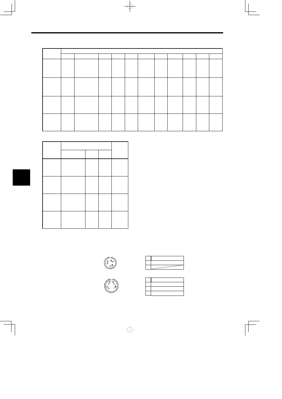
• Connector Wiring on Brake and Motor Sides
Brake terminal
Brake terminal
A
B
C
Phase U
Phase V
Phase W
Frame ground (FG)
A
B
C
D
5