Yaskawa SGDB User Manual
Page 471
5.6 Specifications and Dimensional Drawings of Peripheral Devices
461
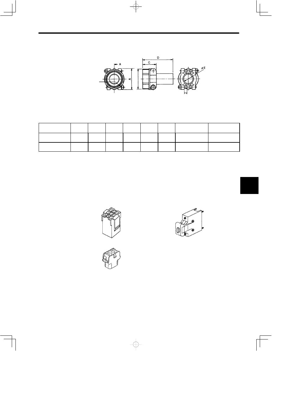
Cable Clamp: JL04-jCK(::)
F (Clamped Range)
Screw W
B
(On
the
Rim)
Dimensions are mm (inches)
Parts Name/Size
A
¦
0.8
(¦0.0315)
B
¦
0.8
(¦0.0315)
C
¦
0.8
(¦0.0315)
D
¦
0.8
(¦0.0315)
ØE
¦
0.8
(¦0.0315)
F
Screw W
Cable Size
JL04-2022CK(14) 37.3
(1.47)
34.9
(1.37)
24.3
(0.96)
53.8
(2.11)
15.9
(0.63)
4 (0.16)
1
3/16-
18UNEF-2B Ø12.9 (0.51)
~Ø15.9 (0.63)
JL04-2428CK(17) 42.9
(42.9)
42.1
(1.66)
26.2
(1.03)
56.2
(2.21)
18
(0.71)
4.8
(0.19)
1
7/16-
18UNEF-2B Ø15 (0.59)~
Ø18 (0.71)
J
For the SGM and SGMP Types
Connector kit comprises three connectors as shown in the diagram below: one encoder
connector at both the motor and SERVOPACK ends of the cable and a motor connector
for the motor end of the cable.
Encoder Connector for Motor End of Cable
Encoder Connector for SERVOPACK End of Cable
Main Circuit (Power Line) Connector on Motor Side
Four types of connector kit are available according to the following criteria:
• Incremental encoder or absolute encoder
• Motor with or without a brake
5