Yaskawa SGDB User Manual
Page 477
5.6 Specifications and Dimensional Drawings of Peripheral Devices
467
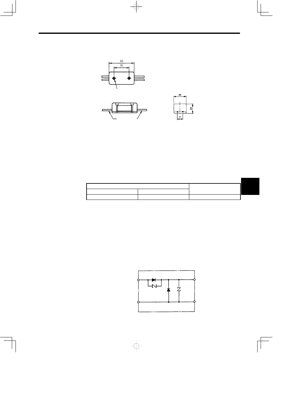
• Dimensional Drawings
Manufactured by Yaskawa Controls Co., Ltd.
Name
Plate
Lead Wires
(1.97)
(1.18)
(0.98)
(0.79)
2-Ø3(2-Ø0.12) MTG HOLES
(SPOT FACING Ø5.5
(Ø0.22), 4 (0.16) LONG)
(0.43)
Dimensions in mm (inches)
• Lead Wire Length: 500 mm each (19.69 in.)
• Max. Ambient Temperature: 60_C
• Lead Wires: Color Code
AC Input
Brake
100V
200V
Blue/White
Yellow/White
Red/Black
NOTE
The internal circuits are shown below. While it is possible to switch either the AC or DC side of
the brake power supply, it is normally safer to switch the AC side. If the DC side is to be
switched, install a surge suppressor near the brake coil to prevent the surge voltages due to
switching the DC side damaging the brake coil. Brake operation time delay occurs during
brake power supply ON/OFF operation. Set output timing of servo OFF operation (motor out-
put stop), referring to “3.4.4 Using Holding Brake.” Especially, if the AC side of the brake pow-
er supply is to be switched, brake operation time is extended.
• Internal Circuit for 200 VAC Input (LPSE-2H01)
Yellow
AC Side
White
Surge
Sup-
pressor
Diode
Red
DC (Brake) Side
Black
5