Yaskawa SGDB User Manual
Page 572
LIST OF USER CONSTANTS
566
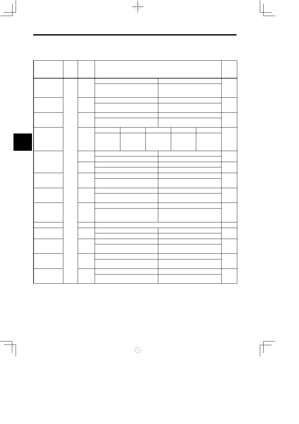
List of Parameters (Memory Switch Setting) (2)
Pa-
rame-
ter
No.
Bit No.
Setting
Facto-
ry Set-
ting
Rotation direc-
i
l
i
Cn-02
0
0
1
0
tion selection
Defines counterclockwise (CCW)
rotation as forward rotation.
Defines clockwise (CW) rotation as
forward rotation (reverse rotation
mode).
Home position
1
0
1
0
p
error proces-
sing selection
Detects home position error (when
absolute encoder is used).
Does not detect home position error.
Analog speed
li i f
i
2
0
1
0
g p
limit function
Does not use analog speed limit
function
Uses analog speed limit function
Reference
l
f
5⋅4⋅3
0⋅0⋅0
0⋅0⋅1
0⋅1⋅0
0⋅1⋅1
1⋅0⋅0
0⋅0⋅0
pulse form
Sign + Pulse CW+CCW
A-phase + B-
phase (x1
multiplica-
tion)
A-phase + B-
phase (x2
multiplica-
tion)
A-phase + B-
phase (x4
multiplica-
tion)
Analog monitor
l
i
6
0
1
0
g
selection
Outputs torque to TRQ-M
Outputs reference speed to TRQ-M
7
0
1
0
Outputs speed to VTG-M
Outputs position error to VTG-M
Analog current
li i f
i
8
0
1
0
g
limit function
Does not use analog current limit
function
Uses analog current limit function
Torque feed-for-
d f
i
9
0
1
0
q
ward function
Does not use torque feed-forward
function
Uses torque feed-forward function
Clear signal
A
0
1
0
g
Clears the error counter when an er-
ror counter clear signal is at high
level
Clears the error counter on the ris-
ing edge of an error counter clear
signal
Reserved
B
Reserved : Setting = 0 (do not change the setting)
0
Torque filter
C
0
1
*
q
Uses torque filter as primary filter
Uses torque filter as secondary filter
Reference
l
f
D
0
1
0
pulse form
Does not invert reference pulse log-
ic
Inverts reference pulse logic
Position error
i
E
0
1
0
monitor
Displays position error in x1 refer-
ence units while in monitor mode
Displays position error in x100 refer-
ence units while in monitor mode
Reference
l
fil
F
0
1
0
pulse filter
Selects filter time constant ’small’.
(450 kpps max)
Selects filter time constant ’large’.
(200 kpps max)
* 5.0 kW or less : 0,
6.0kW or more : 1
NOTE
For the Cn-02 memory switch, always turn the power OFF, then ON after changing the set-
ting. This makes the new setting valid. However, bits 6, 7, E become valid immediately after
setting
C