Output → /bk – Yaskawa SGDB User Manual
Page 122
APPLICATIONS OF Σ-SERIES PRODUCTS
3.4.4 Using Holding Brake cont.
110
J
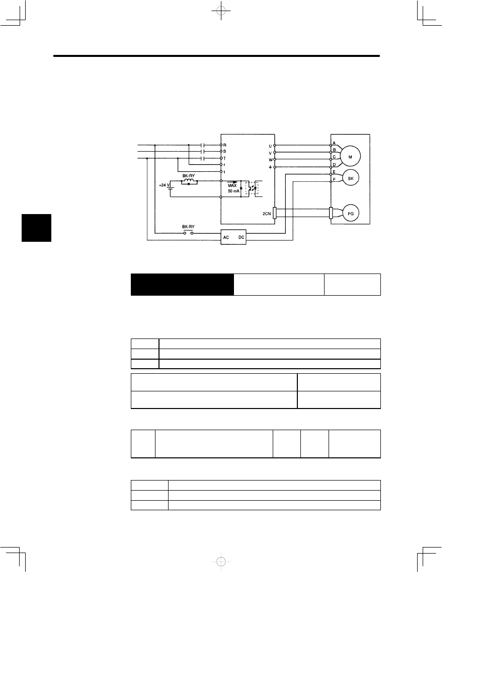
Connection Example
Use SERVOPACK contact output-signal /BK and brake power supply to form a brake
ON/OFF circuit.
An example of standard wiring is shown below.
Power supply
SGDB SERVOPACK
SGMj servomotor
with brake
Blue or
yellow
Red
White
Black
Brake power supply
BK-RY: Brake control relay
Brake power supply has two types (200 V, 100 V).
/BK−
/BK+
Motor plug
Output → /BK
Brake Interlock Output
For Speed/Torque
Control and
Position Control
This output signal controls the brake when a motor with brake is used. This signal termi-
nal need not be connected when a motor without brake is used.
Related Parameters
Cn-12
Time delay from brake signal until servo OFF
Cn-15
Speed level for brake signal output during operation
Cn-16
Output timing of brake signal during motor operation
ON Status:
Circuit is closed or signal is at low level.
Releases the brake.
OFF Status:
Circuit is open or signal is at high level.
Applies the brake.
Set the following parameter to specify the 1CN pin to which the BK signal is output.
Cn-2D
OUTSEL Output Signal Selection
Setting
Range:
110 to
666
Factory
Setting:
210
For
Speed/Torque
Control and
Position Control
This parameter is used to select a function signal as the 1CN output signal.
1s place
Select the 1CN-25 and 1CN-26 (/COIN, /V-CMP) functions.
10s place
Select the 1CN-27 and 1CN-28 (/TGON) functions.
100s place
Select the 1CN-29 and 1CN-30 (/S-RDY) functions.
3