5 minimum parameters required and input signals – Yaskawa SGDB User Manual
Page 61
2.4 Conducting a Test Run
49
NOTE
Check the motor operation with the motor disconnected from the machine. If the host con-
troller does not perform position control correctly, the motor may run out of control.
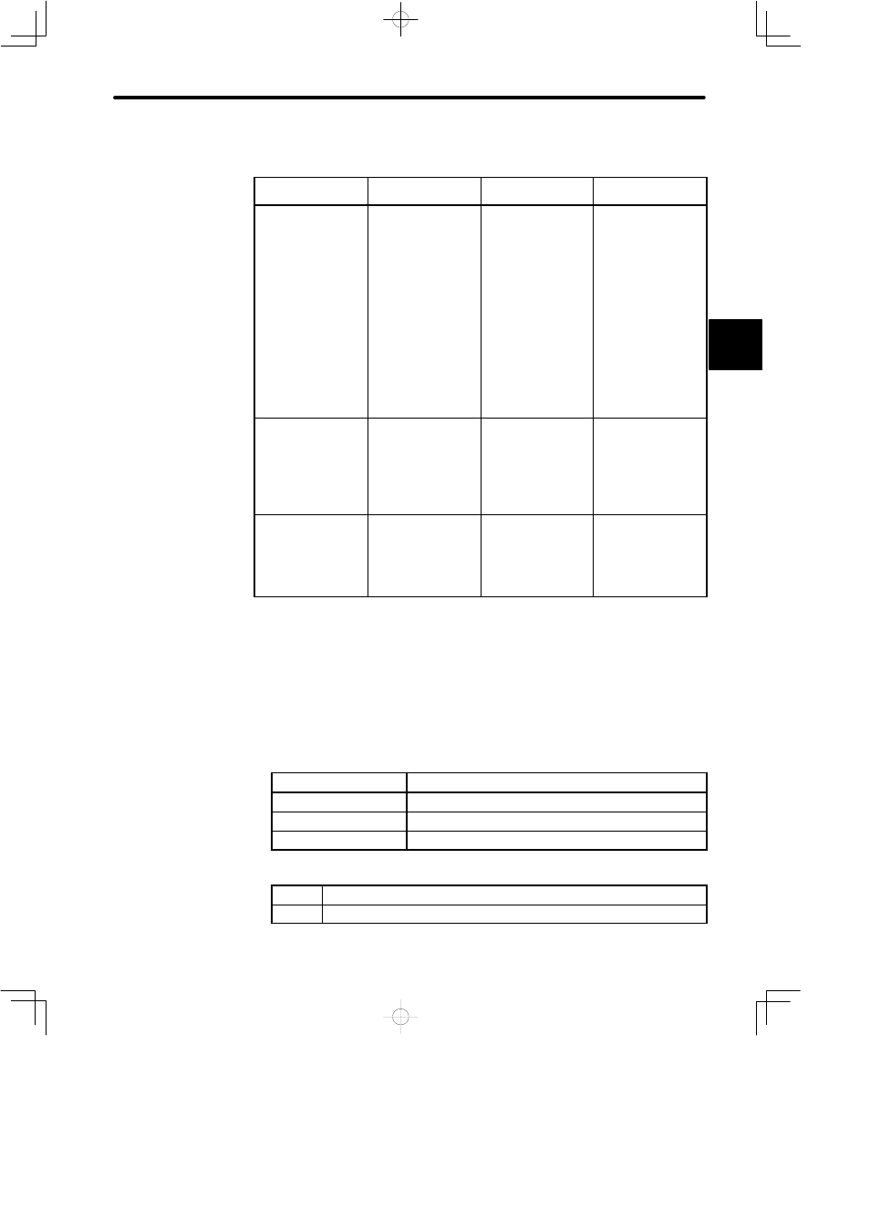
Reference from
Host Controller
Check Items
Check Method
Review Items
Jogging
(constant-speed
reference input from
host controller)
Motor speed
Check the motor
speed as follows:
D
Use the speed
monitor (Un-00) of
the digital operator.
D
Run the motor at
low speed. For
example, input a
speed reference of
60 min
−1
and
check that the
motor makes one
revolution per one
second.
Check whether the
speed reference gain
value (parameter
Cn-03) is correct.
Simple positioning
Number of motor
revolutions
D
Input a reference
equivalent to one
motor revolution
and visually check
that the motor shaft
makes one
revolution.
Check whether the
dividing ratio count
(parameter Cn-0A) is
correct.
Overtravel (when
P-OT and N-OT
signals are used)
Whether the motor
stops rotating when
P-OT and N-OT
signals are input
D
Check that the
motor stops when
P-OT and N-OT
signals are input
during continuous
motor operation.
If the motor does not
stop, review the
P-OT and N-OT
wiring.
2.4.5 Minimum Parameters Required and Input Signals
This section describes the minimum parameters and input signals that must be set to
conduct a test run.
For details on how to set each parameter, refer to Section 4.1.6 Operation in Parameter
Setting Mode.
J
Parameters
• Basic parameters (common to speed, torque, position control)
Cn-11
Number of encoder pulses
Cn-01, bit E
Encoder selection
Cn-2A
Motor selection (check only in substance).
Cn-2C
PG power supply voltage change
• For speed/torque control
Cn-03
Speed reference gain (see page 68)
Cn-0A
Dividing ratio setting
2