Yaskawa SGDB User Manual
Page 560
SERVO ADJUSTMENT
A.4.1 Guidelines for Gain Settings According to Load Inertia Ratio cont.
552
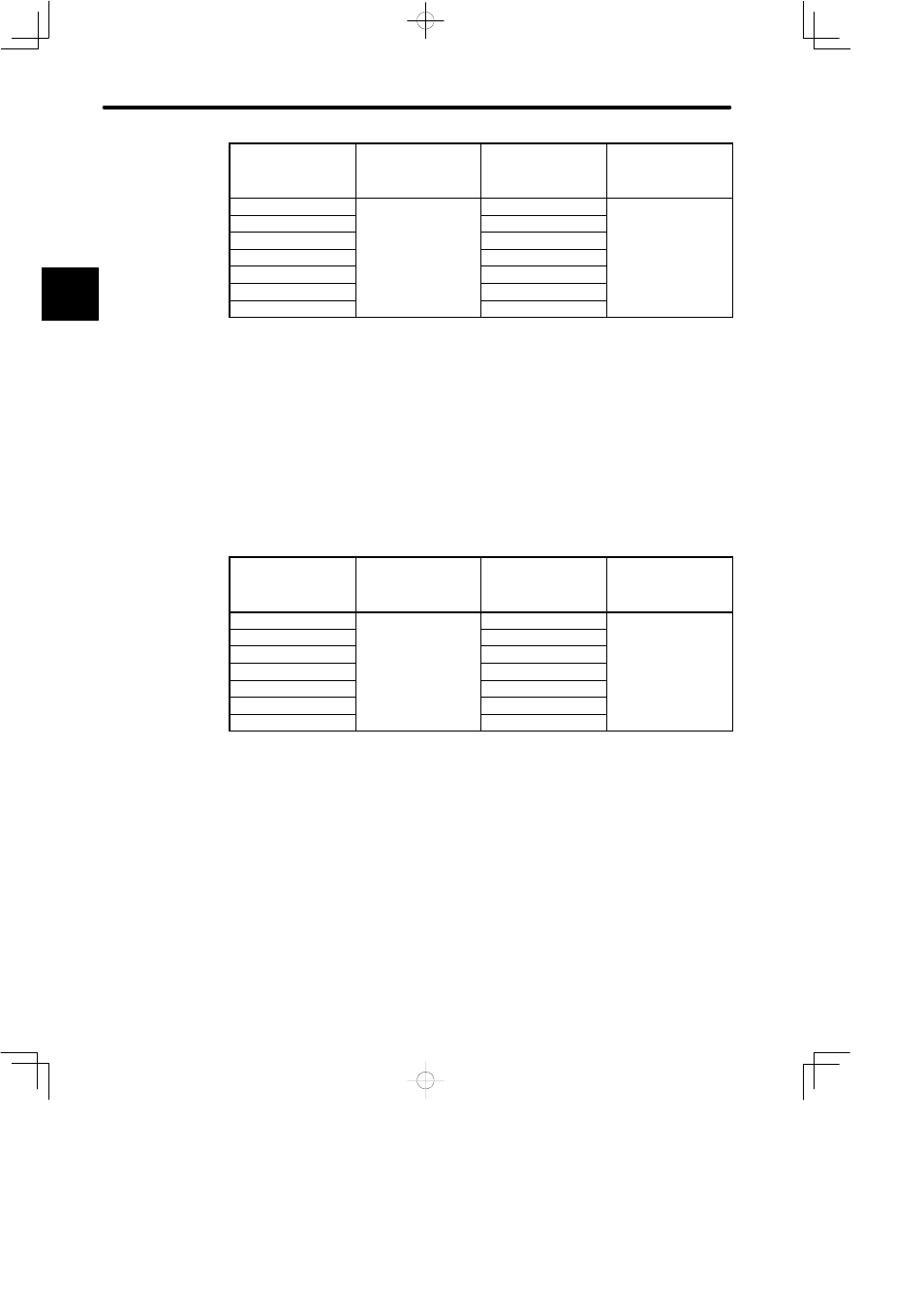
Load/Inertia Ratio
(GD
L
2
/GD
M
2
)
Position Loop Gain
(Cn-1A) [1/s]
Speed Loop Gain
(Cn-04)
Speed Loop
Integration Time
Constant (Cn-05)
[ms]
1 x
30 to 50
30 to 50
10 to 40
3 x
60 to 100
Slightly increase for
5 x
90 to 150
Slightly increase for
inertia ratio of 20 x, or
greater
10 x
160 to 270
greater.
15 x
240 to 400
20 x
310 to 520
30 x
450 to 770
For an inertia ratio of 10 x, or greater, slightly reduce the position loop gain and speed
loop gain below the values shown and set the integration time constant to a higher
value before starting the adjustment.
As the inertia ratio increases, set the position loop gain and speed loop gain to the
lower limit of the range of values specified. Conversely, increase the speed loop in-
tegration time constant.
J
Machines with Low Rigidity
Machines driven by timing belts, chains or wave reduction gears (product name: Har-
monic Drive).
Example: Conveyors, articulated robots
Load/Inertia Ratio
(GD
L
2
/GD
M
2
)
Position Loop Gain
(Cn-1A) [1/s]
Speed Loop Gain
(Cn-04)
Speed Loop
Integration Time
Constant (Cn-05)
[ms]
1 x
10 to 20
10 to 20
50 to 120
3 x
20 to 40
Slightly increase for
5 x
30 to 60
Slightly increase for
inertia ratio of 20 x, or
greater
10 x
50 to 110
greater.
15 x
80 to 160
20 x
100 to 210
30 x
150 to 310
For an inertia ratio of 10 x, or greater, slightly reduce the position loop gain and speed
loop gain below the values shown and set the integration time constant to a higher
value before starting the adjustment.
As the inertia ratio increases, set the position loop gain and speed loop gain to the
lower limit of the range of values specified. Conversely, increase the speed loop in-
tegration time constant.
A