Yaskawa SGDB User Manual
Page 545
INSPECTION, MAINTENANCE, AND TROUBLESHOOTING
6.2.3 Internal Connection Diagram and Instrument Connection Examples cont.
536
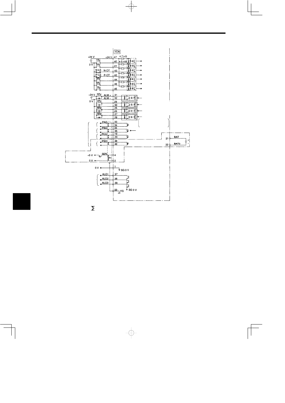
(from previous page)
Servo ON for 1Ry ON
P control for 2Ry ON
Reverse drive disabled for N-LS open
Forward drive disabled for P-LS open
Alarm reset for 3Ry ON
Reverse current limit ON for 6Ry ON
Forward current limit ON for 7Ry ON
5Ry OFF for Servo alarm
4Ry ON for Servo ready
8Ry ON for speed coincidence
9Ry ON for TG ON
PG output line driver
SEN signal
input
Alarm code output
D
Maximum operational voltage = 30VDC
D
Maximum operational current = 20 mA
(Note)1 Signal input line
2 24V power supply must be prepared by customers
represents twisted pair wires
/Servo ON
/P control
Reverse drive disabled
Forward drive disabled
/Alarm reset
/Reverse current limit ON
/Forward current limit ON
Servo alarm
Servo ready Photocoupler output
D
Maximum operational voltage = 30VDC
D
Maximum operational current = 50 mA
Speed
coincidence
/TGON
ON when the motor speed
level (set in parameter)is
exceeded
Line driver
T-I made
SN75ALS194NS
For absolute encoder
Phase A
Phase B
Phase C
Phase S
/S-ON
/ALMRST
/N-CL
/P-CL
/S-RDY+
/S-RDY−
/V-CMP+
/V-CMP−
/TGON+
/TGON−
/PAO
/PBO
/PCO
/PSO
/P-CON
6