Yaskawa SGDB User Manual
Page 136
APPLICATIONS OF Σ-SERIES PRODUCTS
3.6.6 Using Mode Switch cont.
124
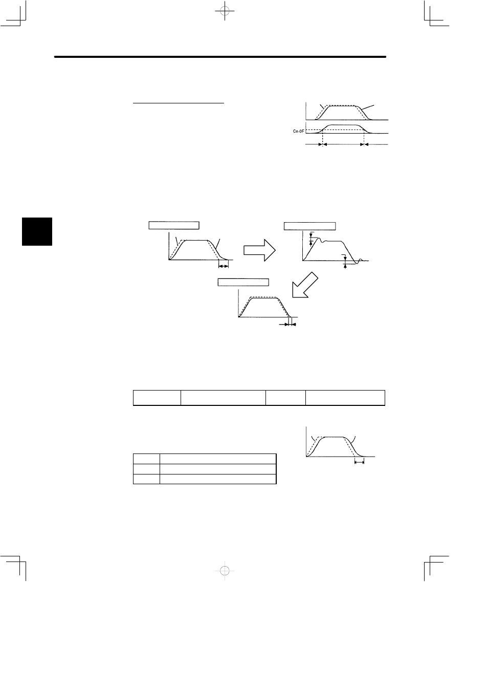
When Error Pulse Is Used as a Detection Point of Mode Switch
This is for position control only.
If an error pulse exceeds the value set in parame-
ter Cn-0F, the speed loop switches to P control.
Example of Use:
The mode switch is used to reduce settling time.
Generally, speed loop gain must be increased to reduce settling time. Using the mode
switch suppresses the occurrence of overshoot and undershoot when speed loop
gain is increased.
Without mode switch
Motor
speed
Speed reference
Motor speed
Settling time is long
Increase speed loop gain
Without mode switch
Motor
speed
Overshoot
Undershoot
Time
Motor speed
Suppress the occurrence
of overshoot and
undershoot.
With mode switch
Settling time
J
Parameters
The parameters required to set each mode switch are summarized as follows.
Cn-01Bit B
Mode Switch ON/OFF
Factory
Setting: 0
For Speed Control and
Position Control
This parameter is used to enable or disable the
mode switch function.
Setting Meaning
0
Uses the mode switch function
1
Does not use the mode switch function
The SERVOPACK allows use of four different
types of mode switch. To select a mode switch, set
bits C and D of memory switch Cn-01.
3
Speed
Speed reference
Motor
speed
Error
pulse
PI control
P control
PI control
Speed Reference
Actual
motor
operation
Time
Settling time
Mode switch is used to reduce settling
time and suppress undershoot when the
motor stops. It switches PI control to P
control when certain conditions are met.