Yaskawa SGDB User Manual
Page 397
5.4 Σ -Series Dimensional Drawings
387
5) The electromagnetic brake is only to hold the load in position and cannot be used to stop
the motor.
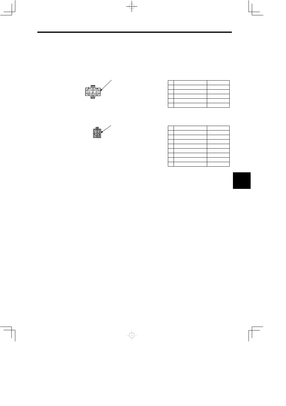
• Details of Motor and Encoder Plugs (Common for 100W (0.13 HP) to 750 W (1.01 HP))
/C channel output
Socket: 350536-6 or 350550-6
Phase U
Red
Phase V
White
Phase W
Blue
FG
Green/Yellow
Motor Plug
Pin: No.1 to No.4
350218-6 or
350547-6
Cap: 350781-1
Encoder Plug
Incremental Encoder Wiring Specifications
A channel output
Blue
/A channel output
Blue/Black
B channel output
Yellow
/B channel output
Yellow/Black
Green
Green/Black
Gray
Red
FG (Frame Ground)
Orange
Plug: 172169-1 (AMP)
Pin: 170359-1 or 170363-1
Plug : 350715-1 (AMP)
Connected to
Connected to
Cap :172161-1
Socket: 170361-1 or 170365-1
1
2
3
4
1
2
3
4
5
6
7
8
9
C channel output
+5V (power supply)
0V (power supply)
Motor Wiring Specifications
Brake terminal
Black
5
Brake terminal
Black
6
Pin: No.5 to No.6
350561-1 or
350690-1
5