Yaskawa SGDB User Manual
Page 47
2.3 Connection and Wiring
35
Form a power ON sequence as follows:
• Form a power ON sequence so that the power is turned OFF when a servo alarm signal
is output. (See the circuit diagram shown on the previous page.)
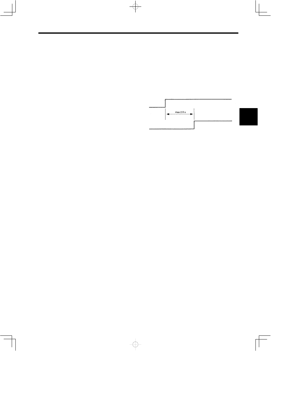
• Hold down the power ON push-button for at least two seconds. The SERVOPACK out-
puts a servo alarm signal for approximately two seconds or less when the power is
turned ON. This operation is required to initialize the SERVOPACK.
Servo alarm (ALM) output signal
Power supply
NOTE
• Do not wire power lines and signal lines in the same duct or bundle them together.
Wire such that signal lines are kept apart from power lines by at least 30 cm.
• Twisted pair wire and multi-core twisted pair shielding wires should be used for signal
lines, encoder (PG) feedback line.
The length for wiring is 3 m maximum for the reference input line, 20 m maximum for the
PG feedback line.
• Do not touch the power terminal even if power was turned OFF.
High voltage may still remain in SERVOPACK.
Perform inspection only after the CHARGE lamp is OFF.
• Avoid frequently turning the power ON and OFF. Since the SERVOPACK has a capaci-
tor in the power supply, a high charging current flows (for 0.2 second) when the power is
turned ON. Therefore, frequently turning the power ON and OFF causes the main cir-
cuit devices (such as capacitors and fuses) to deteriorate, resulting in unexpected
problems.
2