1 cable specifications and peripheral devices – Yaskawa SGDB User Manual
Page 452
SERVO SELECTION AND DATA SHEETS
5.6.1 Cable Specifications and Peripheral Devices
442
5.6
Specifications and Dimensional Drawings of Peripheral
Devices
This section shows the specifications and dimensional drawings of the peripheral devices
required for the Σ-Series servo system. The sequence of peripheral devices is given by the
Flowchart for Peripheral Device Selection in Section 5.5.1 Selecting Peripheral Devices.
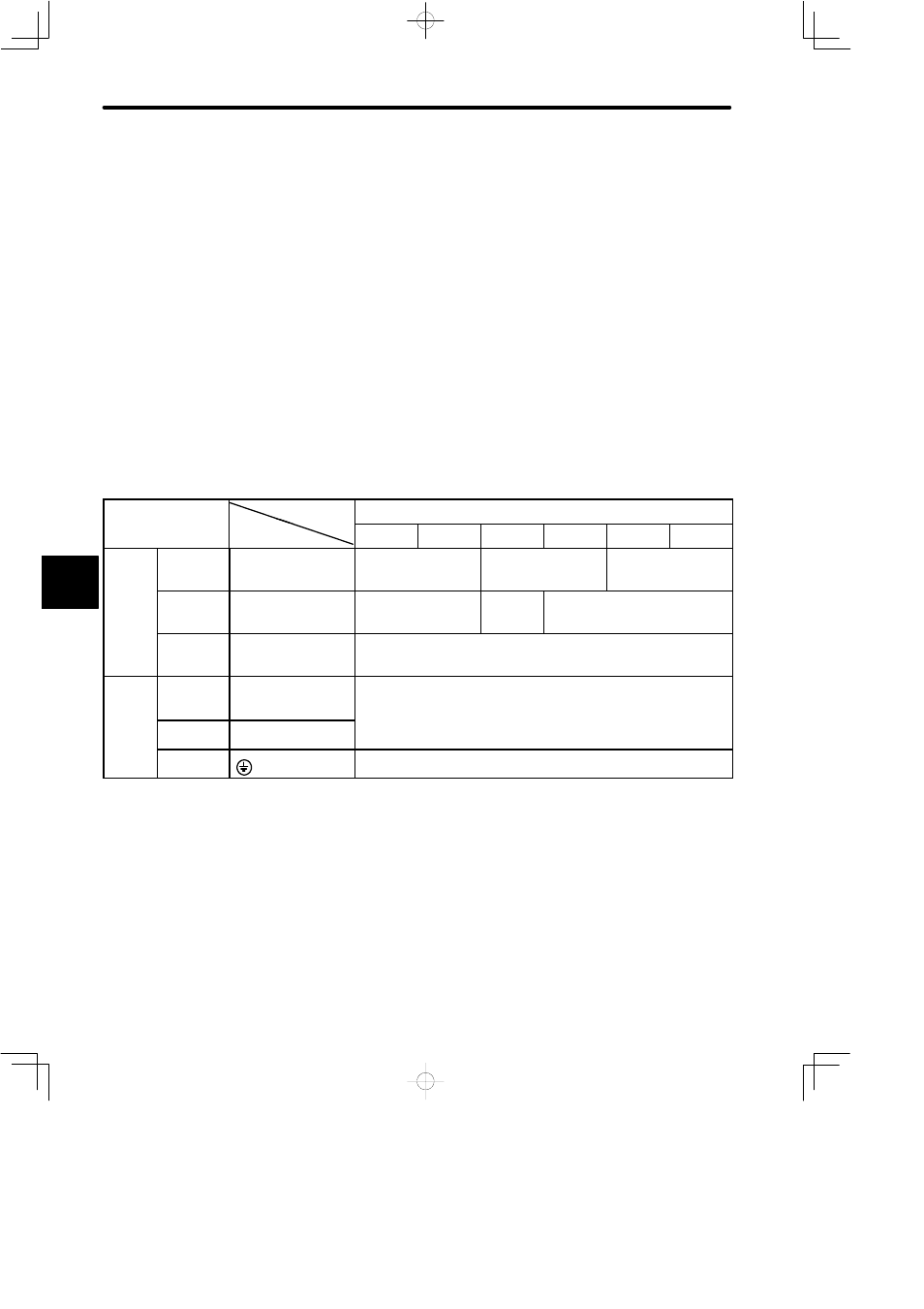
5.6.1 Cable Specifications and Peripheral Devices
The cable sizes and peripheral devices for SGDB SERVOPACKs are listed in the follow-
ing tables.
The cable specifications were selected under conditions of three cables per bundle at an
ambient temperature of 40_, with the rated current flowing.
J
Cable Size
External
Terminal Name
SGDB Type
Terminal
Cable Size (mm
2
)
Terminal Name
Terminal
Symbol
03AD
05AD
07AD
10AD
15AD
20AD
On-line
Terminal
Main Circuit
Power Input
Terminal
R, S, T
HIV 1.25 or more
HIV 2.0 or more
HIV 3.5 or more
Motor
Connection
Terminal
U, V, W
HIV 1.25 or more
HIV 2.0 or
more
HIV 3.5 or more
Control
Power Input
Terminal
r, t
HIV 1.25 or more
Off-line
Terminal
Control I/O
Signal
Connector
1CN
Core of twisted pair or twisted pair shield wires: 0.12 mm
2
or more
Outside dimensions of tinned annealed copper twisted wires:
max. Ø16 (for 1CN), max. Ø11 (for 2CN)
PG Signal
Connector
2CN
(
),
(
)
Ground
Terminal
HIV 2.0 or more
5