520 j a.c1 – Yaskawa SGDB User Manual
Page 529
INSPECTION, MAINTENANCE, AND TROUBLESHOOTING
6.2.1 Troubleshooting Problems with Alarm Display cont.
520
J
A.C1
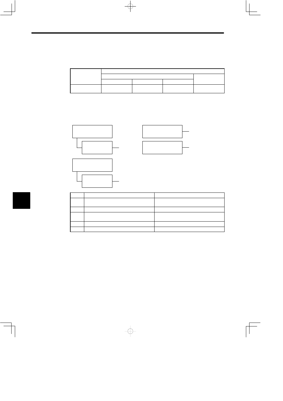
Display and Outputs
Digital Operator
Di l
d
Alarm Output
g
p
Display and
Alarm Name
Alarm Code Output
Alarm Output
Alarm Name
ALO1
ALO2
ALO3
p
A.C1
Servo overrun
ON
OFF
ON
OFF
OFF: Output transistor is OFF
ON: Output transistor is ON
Status When Alarm Occurred
E
At power ON
Parameter Cn-01
Bit 0 = 0
When servo ON (/S-ON)
signal turned ON
A
,
B
, C, D, E
On speed reference input
A
,
B
, C, D, E
A
,
B
, C, D, E
Occurred 1 to 3 se-
conds after power ON
Parameter Cn-01
Bit 0 = 1
Cause
Remedy
A
Servomotor wiring incorrect or
disconnected
Check wiring and connectors at
servomotor.
B
Encoder wiring incorrect or disconnected
Check wiring and connectors at encoder.
C
Incremental encoder power not supplied
from SERVOPACK.
Use the SERVOPACK power supply for
the encoder.
D
Encoder defective
Replace servomotor.
E
Circuit board (1PWB) defective
Replace SERVOPACK.
6