Yaskawa SGDB User Manual
Page 81
3.2 Setting Parameters According to Host Controller
69
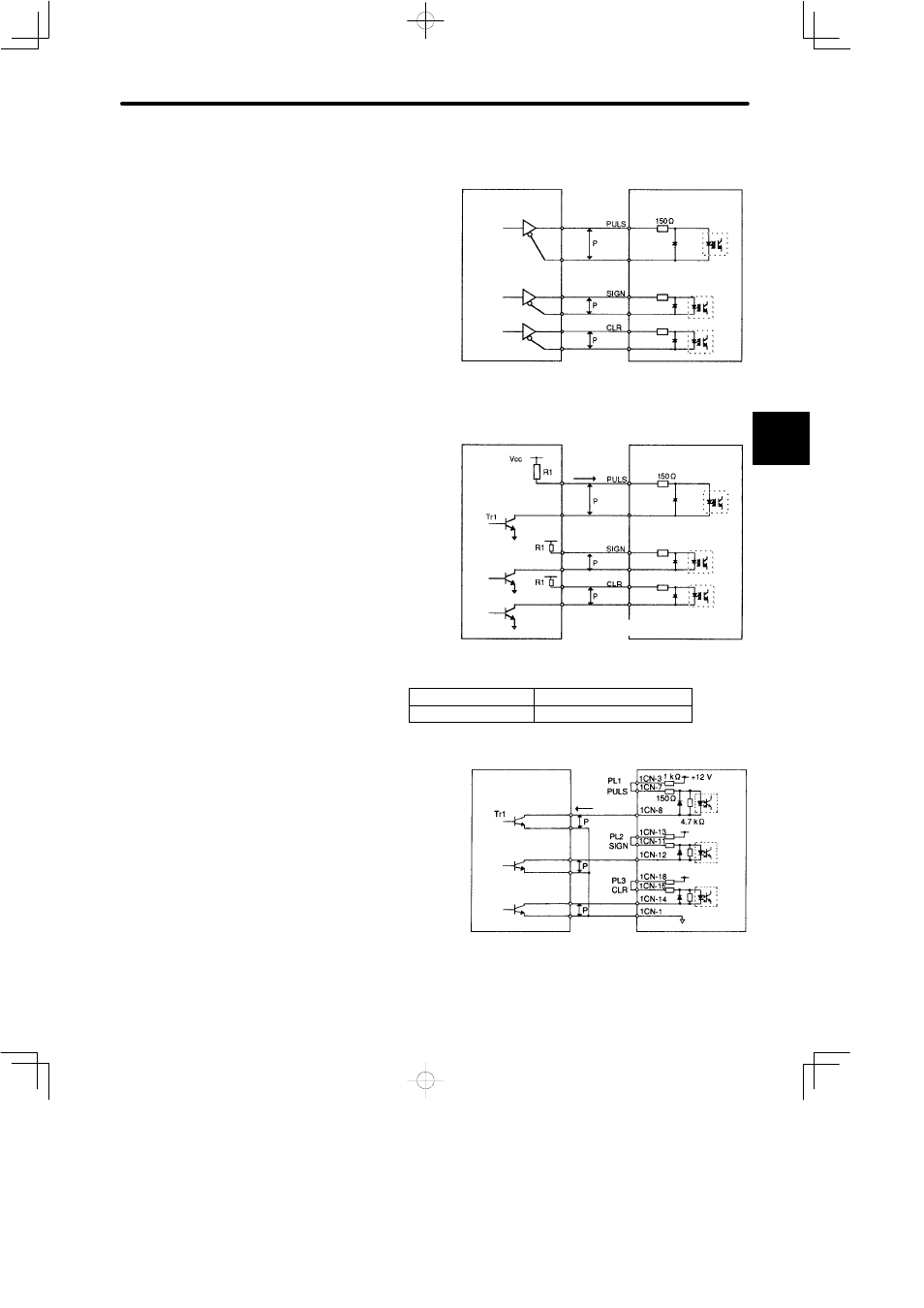
Connection Example 1: Line Driver Output
Line Driver Used:
SN75174 manufactured by
Texas Instruments Inc., or
MC3487 or equivalent.
Connection Example 2: Open Collector Output
Sets the value of limiting re-
sistor R1 so that input cur-
rent i falls within the following
range:
Input Current i: 7 to 15 mA
Examples:
• When Vcc is 12 V,
R1 = 1 kΩ
• When Vcc is 5 V,
R1 = 180 Ω
Note The signal logic for open collector output is as follows.
When Tr1 is ON
Equivalent to high level input
When Tr1 is OFF
Equivalent to low level input
The power supply inside the
SERVOPACK can be used.
If this power supply is used, it
will not be isolated from 0 V
in the SERVOPACK.
3
Host controller
Line driver
Photocoupler
1CN-7
1CN-8
1CN-11
1CN-12
1CN-15
1CN-14
SGDB SERVOPACK
/PULS
/SIGN
/CLR
Host controller
Photocoupler
↕P: Represents twisted-pair cables
i
1CN-7
1CN-8
1CN-11
1CN-12
1CN-15
1CN-14
SGDB SERVOPACK
/PULS
/SIGN
/CLR
Host controller
SGDB SERVOPACK
Photocoupler
About 9mA
1.5 V or less
when ON
/PULS
/SIGN
/CLR