Inspection, maintenance, and troubleshooting, 0kw to 15.0 kw – Yaskawa SGDB User Manual
Page 543
INSPECTION, MAINTENANCE, AND TROUBLESHOOTING
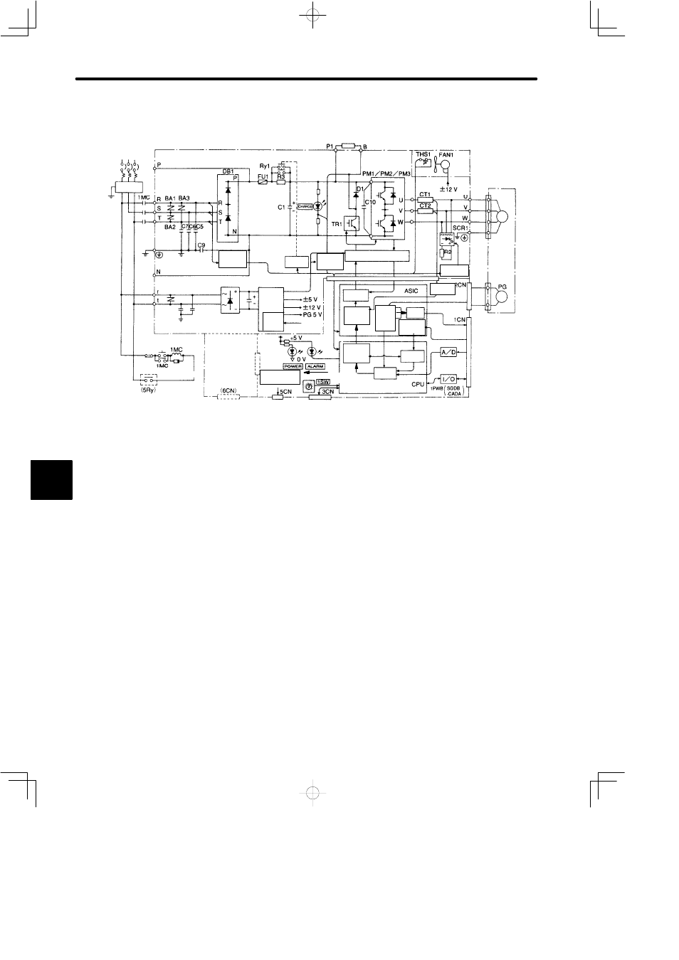
6.2.3 Internal Connection Diagram and Instrument Connection Examples cont.
534
• 6.0kW to 15.0 kW
Voltage
detection
isolator
Three-phase
200 to 230VAC
(50/60 Hz)
Line filter
Power
ON
Power
OFF
Surge
suppressor
Open when
Servo alarm
occurs.
Voltage
detection
isolator
Optional
printed board
(not mounted)
Analog voltage
conversion
Analog monitor
output for observation
Relay
driver
Base driver, Overcurrent
protection isolator
PMW
generator
Digital
current
amplifier
Current
reference
operation
selection
Axis address
Serial port
Speed
control
Position
control
PG
signal
proces-
sing
Divi-
der
Reference
pulse pro-
cessing
Servomotor
(PG output)
(Reference pulse
input)
(Speed/torque
reference input)
(Sequence
input/output)
Digital operator,
personal computer
Gate driver
isolator
Current
detection
DC/DC
conver-
sion
Voltage
adjust-
ment
Regenerative resistor (option)
+10
−15
%
6