A.4 gain setting references – Yaskawa SGDB User Manual
Page 559
A.4 Gain Setting References
551
A.4 Gain Setting References
This section presents tables of load inertia values for reference when adjusting the gain.
A.4.1 Guidelines for Gain Settings According to Load Inertia Ratio
Adjustment guidelines are given below according to the rigidity of the mechanical system
and load inertia. Use these values as guidelines when adjusting according to the proce-
dures described above.
These values are given as guidelines only. Oscillations and poor response may occur
inside the specified value ranges. Observe the response (waveform) when optimizing
the adjustment.
Higher gains are possible for machines with high rigidity.
J
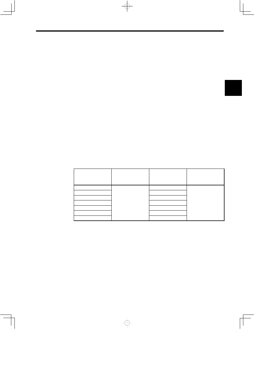
Machines with High Rigidity
Ball Screw, Direct Drive Machines
Example: Chip mounter, IC bonder, precision machine tools
Load/Inertia Ratio
(GD
L
2
/GD
M
2
)
Position Loop Gain
(Cn-1A) [1/s]
Speed Loop Gain
(Cn-04)
Speed Loop
Integration Time
Constant
(Cn-05) [ms]
1 x
50 to 70
50 to 70
5 to 20
3 x
100 to 140
Slightly increase for
5 x
150 to 200
Slightly increase for
inertia ratio of 20 x, or
greater
10 x
270 to 380
greater.
15 x
400 to 560
20 x
500 to 730
30 x
700 to 1100
For an inertia ratio of 10 x, or greater, slightly reduce the position loop gain and speed
loop gain below the values shown and set the integration time constant to a higher
value before starting the adjustment.
As the inertia ratio increases, set the position loop gain and speed loop gain to the
lower limit of the range of values specified. Conversely, increase the speed loop in-
tegration time constant.
J
Machines with Medium Rigidity
Machines driven by ball screw through reduction gears, or machines directly driven
by long ball screws.
Example: General machine tools, orthogonal robots, conveyors
A