522 j a.c3 – Yaskawa SGDB User Manual
Page 531
INSPECTION, MAINTENANCE, AND TROUBLESHOOTING
6.2.1 Troubleshooting Problems with Alarm Display cont.
522
J
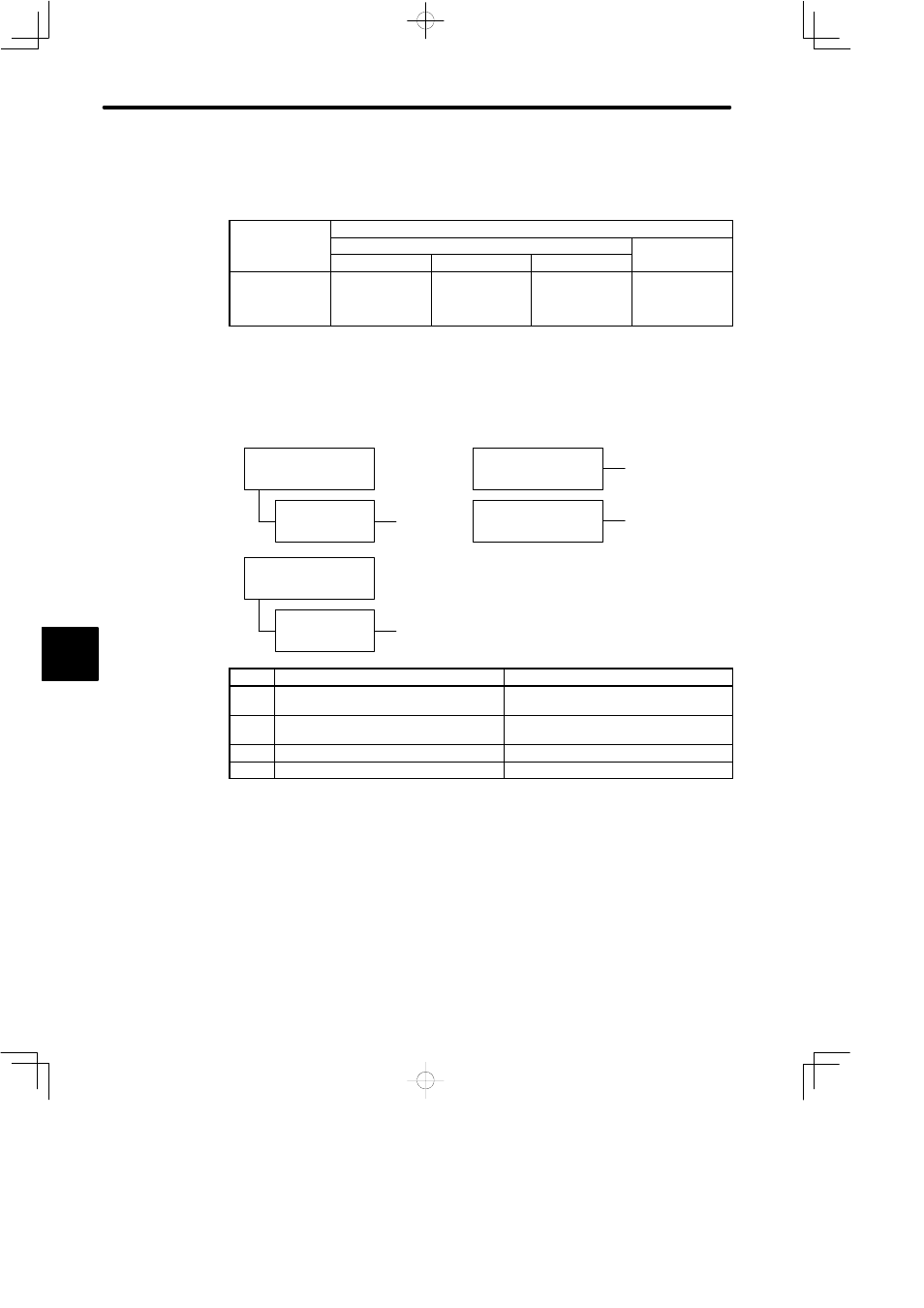
A.C3
Display and Outputs
Digital Operator
Di l
d
Alarm Output
g
p
Display and
Alarm Name
Alarm Code Output
Alarm Output
Alarm Name
ALO1
ALO2
ALO3
p
A.C3
Encoder A-,
B-phase
disconnection
ON
OFF
ON
OFF
OFF: Output transistor is OFF
ON: Output transistor is ON
Status When Alarm Occurred
D
At power ON
Parameter Cn-01
Bit 0 = 0
When servo ON (/S-ON)
signal turned ON
A
, B, C, D
During servomotor
operation
A, B, C, D
A
, B, C, D
Occurred 1 to 3 seconds
after power ON
Parameter Cn-01
Bit 0 = 1
Cause
Remedy
A
Encoder wiring incorrect or poor
connection
Check wiring and connectors at encoder.
B
Noise in encoder wiring.
Separate encoder wiring from main wiring
circuits.
C
Encoder defective
Replace servomotor.
D
Circuit board (1PWB) defective
Replace SERVOPACK.
6