Yaskawa SGDB User Manual
Page 137
3.6 Minimizing Positioning Time
125
Cn-01 Bit C
Mode Switch Selection
Factory
Setting: 0
For Speed Control and
Position Control
Cn-01 Bit D
Mode Switch Selection
Factory
Setting: 0
For Speed Control and
Position Control
Use the following parameters to set the mode switch to be used.
Memory
Switch
Cn-01
Mode Switch Type
Parameter for
Setting Detec-
tion Point
Bit D Bit C
tion Point
0
0
Uses torque reference as a detection point.
Cn-0C
0
1
Uses speed reference as a detection point.
Cn-0D
1
0
Uses acceleration reference as a detection point.
Cn-0E
1
1
Uses error pulse as a detection point.
Cn-0F
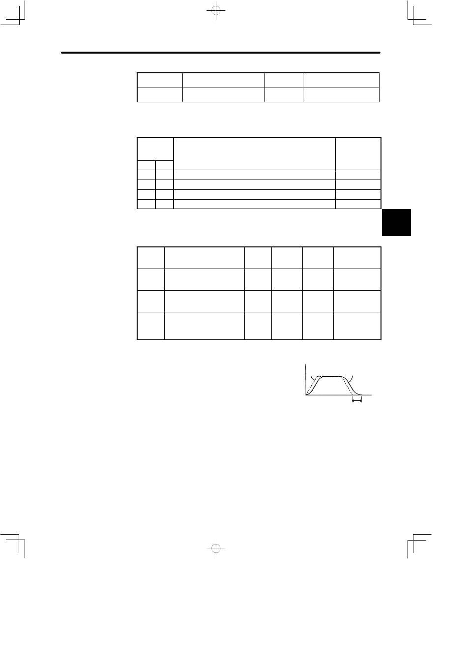
Mode switch is used to reduce settling time and suppress undershoot when the motor
stops. It switches PI control to P control when certain conditions are met.
Cn-0C
TRQMSW Mode Switch
(Torque
Reference)
Unit: %
Setting
Range: 0
to 800
Factory
Setting:
200
For Speed
Control and
Position Control
Cn-0D
REFMSW
Mode Switch
(Speed
Reference)
Unit:
min
−1
Setting
Range: 0
to 10000
Factory
Setting: 0
For Speed
Control and
Position Control
Cn-0E
ACCMSW Mode Switch
(Acceleration
Reference)
Unit: 10
(min
−1
)/
s
Setting
Range: 0
to 3000
Factory
Setting: 0
For Speed
Control and
Position Control
Cn-0F
ERPMSW Mode Switch
(Error Pulse)
Unit:
Refer-
ence
Unit
Setting
Range: 0
to 10000
Factory
Setting:
10000
For Position
Control Only
Mode switch is used to reduce settling time and
suppress undershoot when the motor stops. It
switches PI control to P control when certain
conditions are met.
The SERVOPACK allows use of four different
types of mode switch. To select a mode switch, set
bits B, C and D of memory switch Cn-01.
3
Speed
Reference
Actual motor
operation
Time
Settling time