Yaskawa SGDB User Manual
Page 578
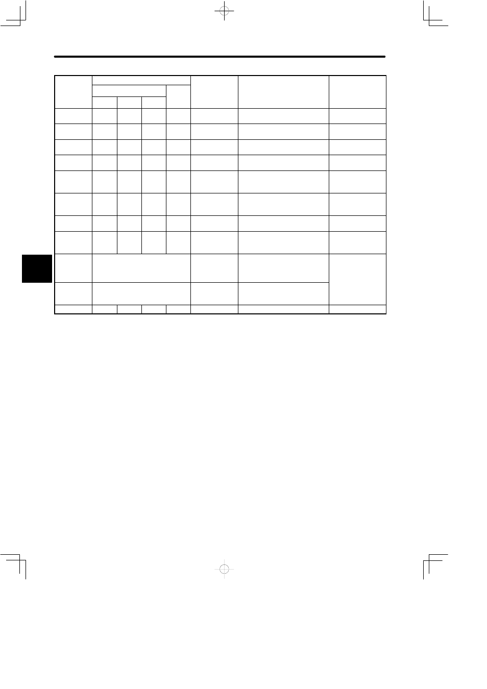
LIST OF ALARM DISPLAYS
572
Alarm Dis-
l
Alarm Output
Alarm Name
Meaning
Remarks
play on
Digital Op-
Alarm Code Output
ALM
Out-
g
Digital Op
erator
ALO1
ALO2
ALO3
Out-
put
A.A1
ON
ON
ON
OFF
Heat sink over-
heated
Heat sink of SERVOPACK was
overheated
A.b1
OFF
OFF
OFF
OFF
Reference in-
put read error
SERVOPACK CPU failed to de-
tect reference input.
A.C1
ON
OFF
ON
OFF
Servo overun
detected
The servomotor (encoder) ran
out of control.
A.C2
ON
OFF
ON
OFF
Encoder output
phase error
Phases A, B and C output by
the encoder are abnormal.
A.C3
ON
OFF
ON
OFF
Encoder A-, B-
phase discon-
nection
Wiring in encoder phase A or B
is disconnected.
A.C4
ON
OFF
ON
OFF
Encoder C-
phase discon-
nection
Wiring in encoder phases C is
disconnected.
A.F1
OFF
ON
OFF
OFF
Power lines
open phase
One phase is not connected in
the main power supply
A.F3
OFF
ON
OFF
OFF
Power loss er-
ror
A power interruption exceeding
one cycle occurred in AC power
supply.
only when bit 5 of
Cn-01 set to 1
CPF00
Undefined
Digital operator
transmission
error 1
Digital operator fails to commu-
nicate with SERVOPACK even
five seconds after power is
turned ON.
These alarms are
not stored in alarm
trace-back
memory.
CPF01
Undefined
Digital operator
transmission
error 2
Transmission error has oc-
curred five consecutive times.
y
A.99
OFF
OFF
OFF
ON
Not an error
Normal operation status
OFF:
Output transistor is OFF
ON:
Output transistor is ON
D