Yaskawa SGDB User Manual
Page 372
USING THE DIGITAL OPERATOR
5.4.1 Servomotor Dimensional Drawings cont.
362
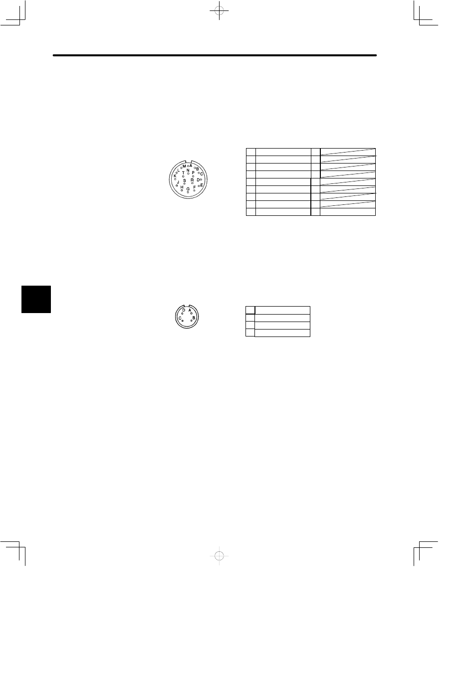
• Connector Wiring on Detector Side
Receptacle: MS3102A20-29P
Plug (To be prepared by customer) (L type): MS3108B20-29S or
(Straight type) MS3106B20-29S
Cable Clamp: (To be prepared by customer) MS3057-12A
/C channel output
Encoder Wiring Specifications
A channel output
/A channel output
B channel output
/B channel output
FG (Frame Ground)
A
B
C
D
E
F
G
H
J
C channel output
+5V DC
0V
K
L
P
R
S
T
M
N
Note
1) Terminals K to T are not used. Do not connect anything.
2) Receptacle, plug and cable clamp are common regardless of motor capacity.
• Connector Wiring on Motor Side
Phase U
Phase V
Phase W
Ground terminal
Motor Wiring Specifications
A
B
C
D
Note
Receptacle, plug and cable clamp differ depending on the capacity. Refer to 6) Connectors
on Detector and Motor Sides (page 392).
5