8 handling of power loss – Yaskawa SGDB User Manual
Page 153
3.7 Forming a Protective Sequence
141
Preset
Value
Function
0
/COIN, /V-CMP
(Can be allocated to 1CN-25 and 1CN-26 only.)
1
/TGON
2
/S-RDY
3
/CLT
4
/BK
5
Overload warning
6
Overload alarm
3.7.8 Handling of Power Loss
Use the following memory switch to specify whether to output a servo alarm when power
loss occurs.
Cn-01 Bit 5
Operation to Be Performed at
Recovery from Power Loss
Factory
Setting: 0
For Speed/Torque Control
and Position Control
If the SGDB SERVOPACK detects instantaneous
voltage drop in power supply, it can output servo
alarm A.F3 to prevent a hazardous situation. This
memory switch is used to specify whether to out-
put this alarm.
Setting
Meaning
0
Does not output a servo alarm after recovery from power loss.
1
Outputs a servo alarm after recovery from power loss.
Normally, set this memory switch to 0. If the /S-RDY signal is not to be used, set the
memory switch to 1. The /S-RDY signal remains OFF while the main power supply is
OFF, regardless of the memory switch setting.
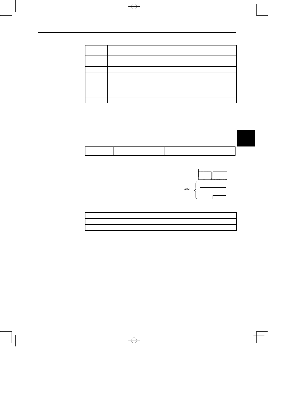
3
200 V
supply
voltage
Power loss
Cn-01 bit 5 = 0
Cn-01 bit 5 = 1
(1CN-31)