Yaskawa SGDB User Manual
Page 110
APPLICATIONS OF Σ-SERIES PRODUCTS
3.2.11 Using the Reference Pulse Input Filter Selection Function
98
J
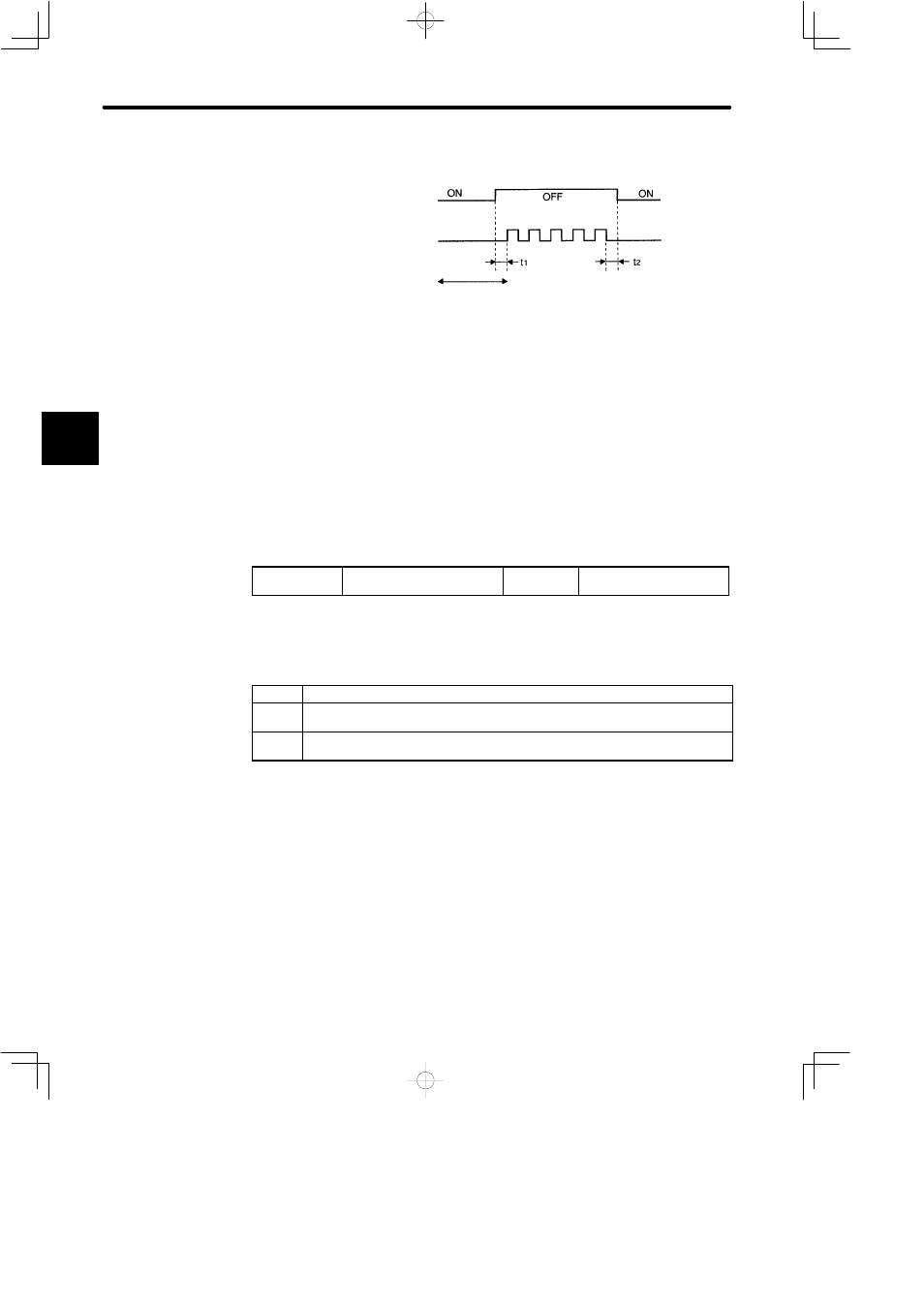
Relationship between INHIBIT Signal and Reference Pulse
/INHIBIT signal
(/P-CON)
Reference pulse
Input reference pulses
are not counted
during this period.
t1, t2 ² 0.5 ms
3.2.11 Using the Reference Pulse Input Filter Selection Function
This function selects a reference pulse input filter inside the SERVOPACK according to
the output form of reference pulses from the host controller.
J
How to Use Reference Pulse Input Filter
Set the following memory switch according to the output form of reference pulses from
the host controller:
Cn-02 Bit F
Reference Pulse Input Filter
Selection Function
Factory
Setting: 0
For Position Control Only
Sets the memory switch according to the output form (line driver or open collector) of ref-
erence pulses from the host controller.
Setting
Meaning
0
Output form of reference pulses from host controller: Line driver output (maximum
frequency of reference pulse: 450 kpps)
1
Output form of reference pulses from host controller: Open collector output
(maximum frequency of reference pulse: 200 kpps)
For open collector output, the wire length must be as short as possible (maximum 3 m).
3