2 setting parameters according to host controller, 1 inputting speed reference – Yaskawa SGDB User Manual
Page 76
APPLICATIONS OF Σ-SERIES PRODUCTS
3.2.1 Inputting Speed Reference
64
3.2
Setting Parameters According to Host Controller
This section describes how to connect a Σ-series Servo to a host controller and how to set
parameters.
3.2.1 Inputting Speed Reference
Input a speed reference by using the following input signal “speed reference input.” Since
this signal can be used in different ways, set the optimum reference input for the system
to be created.
Torque reference input
(analog voltage input)
Speed reference input
(analog voltage input)
SGDB SERVOPACK
Torque
reference
Speed
reference
↕P: Represents twisted-pair cables
1CN-9
1CN-10
1CN-5
1CN-6
→ Input V-REF
1CN-5
Speed Reference Input
For Speed Control
Only
→ Input SG
1CN-6
Signal Ground for Speed
Reference Input
For Speed Control
Only
Use these signals when speed control (analog
reference) mode is selected (Cn-2B is set to 0, 4,
7, 9, or 10).
For ordinary speed control, always wire the V-
REF and SG terminals.
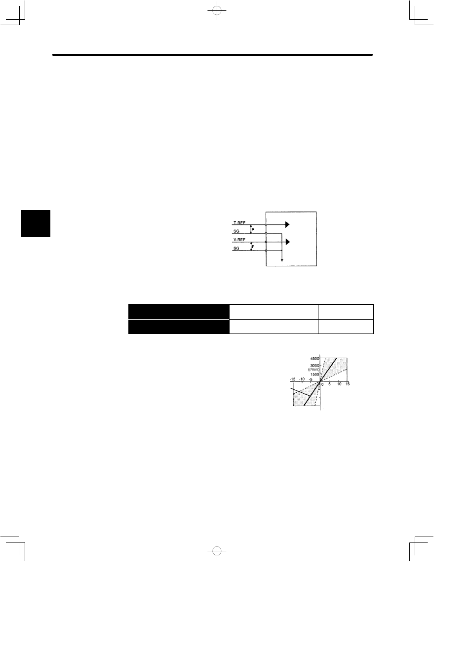
Motor speed is controlled in proportion to the input
voltage between V-REF and SG.
J
Standard Example:
Cn-03 = 500:
This setting means that 6 V is 3000 min
−1
Examples:
+6 V input → 3000 min
−1
in forward direction
+1 V input → 500 min
−1
in forward direction
−3 V input → 1500 min
−1
in reverse direction
Parameter Cn-03 can be used to change the voltage input range.
3
Reference
speed
Standard
setting
Input voltage (V)
Set the slope in
Cn-03 (VREFGN).
−1500
−3000
−4500