4 using regenerative resistor units – Yaskawa SGDB User Manual
Page 163
3.8 Special Wiring
151
3.8.4 Using Regenerative Resistor Units
SERVOPACKs of 6.0 kW or higher have no built-in regenerative resistor. For such SER-
VOPACKs, connect an external regenerative resistor unit.
J
Connecting a Regenerative Resistor Unit
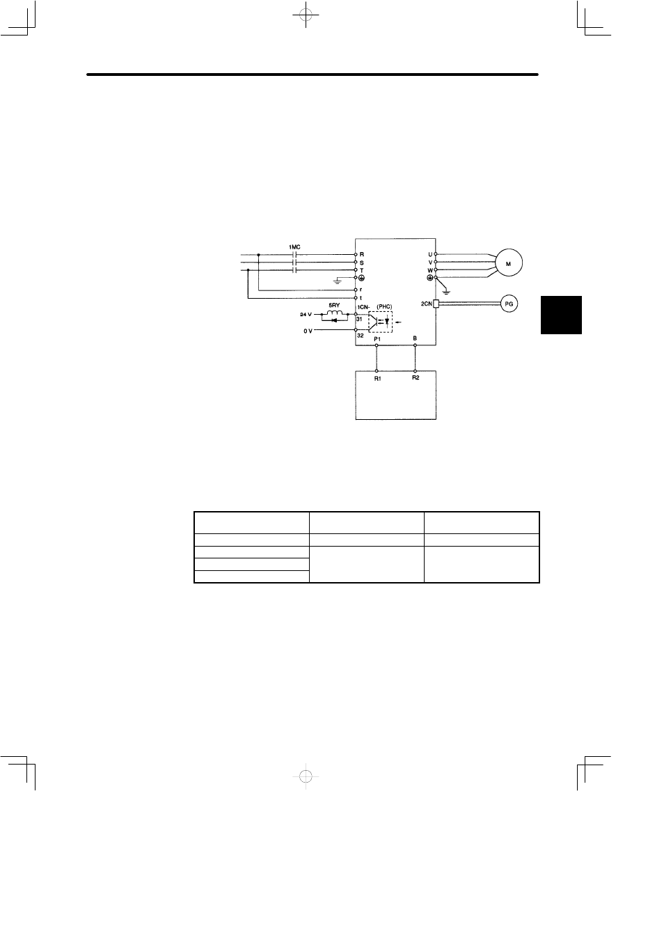
The standard connection diagram for a regenerative resistor unit is shown below.
Three-phase
200-230 VAC
SERVOPACK
Alarm
Regenerative resistor unit
Connecting a Regenerative Resistor Unit
J
Regenerative Resistor Units
SERVOPACK Type
Regenerative Resistor Unit
Type
Regenerative Resistance
(Ω)
SGDB-60ADj
JUSP-RA04
6.25
SGDB-75ADj
JUSP-RA05
3.13
SGDB-1AADj
SGDB-1EADj
NOTE
A regenerative resistor unit becomes very hot under some regenerative operation condi-
tions of the servo system. Therefore, provide a cooling mechanism for the regenerative
resistor unit, use heat resistant and incombustible cables, and route the cables so that
they are not in contact with the unit.
The resistor specifications of each regenerative resistor unit are as follows:
JUSP-RA04 Type: 25
Ω
(220 W) x 4 (connected in parallel)
JUSP-RA05 Type: 25
Ω
(220 W) x 8 (connected in parallel)
3