Yaskawa SGDB User Manual
Page 280
USING THE DIGITAL OPERATOR
5.2.2 Mechanical Characteristics cont.
270
J
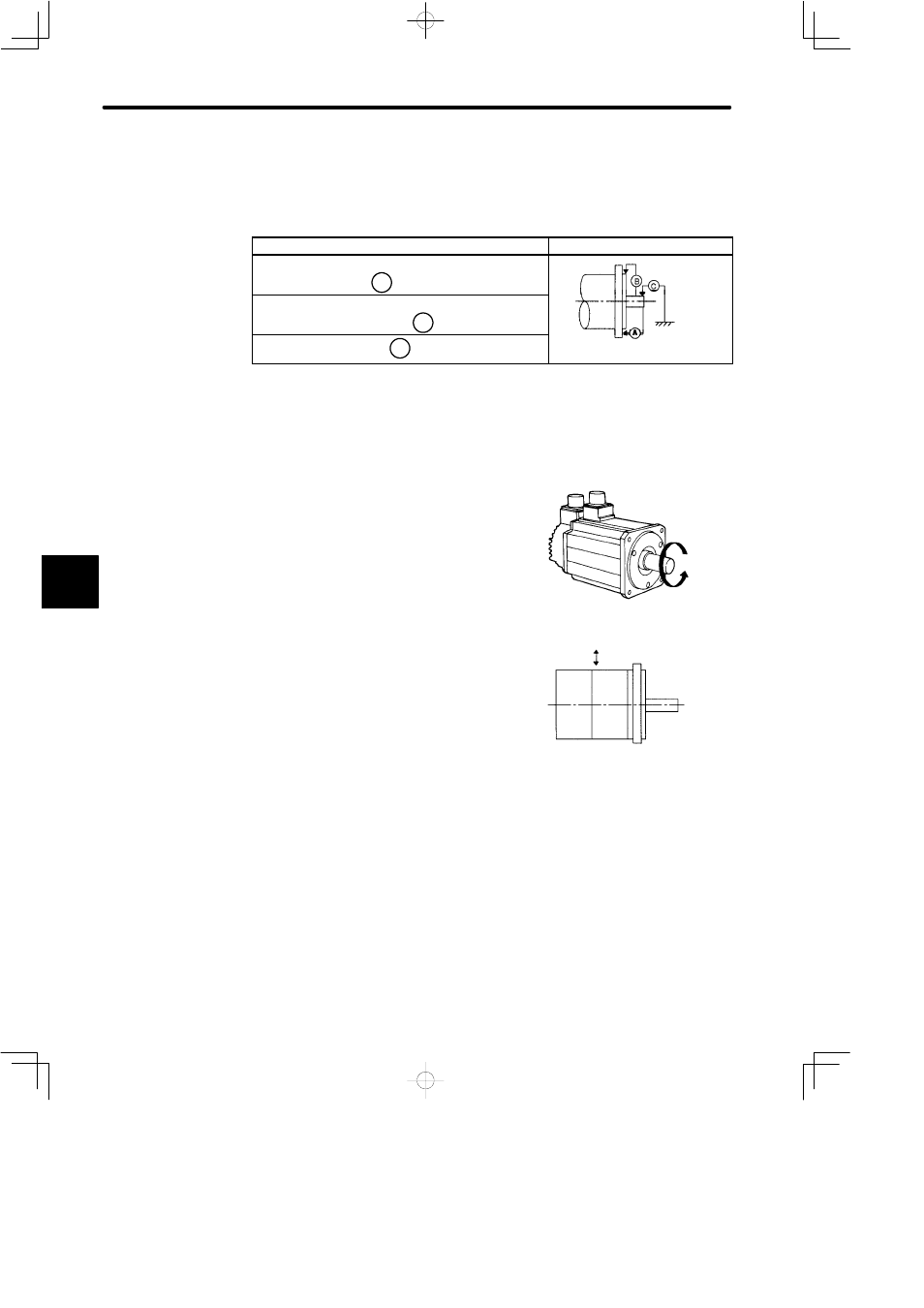
Mechanical Tolerance
The tolerances of the SGMj servomotor output shaft and installation are shown in the
table below.
Tolerance (T.I.R.)
Reference Diagram
Perpendicularity between flange
face and output shaft
A
0.04mm
(0.0016in.)
Mating concentricity of flange O.D.
B
0.04mm
(0.0016in.)
Run-out at end of shaft
C
0.02mm*
(0.00079in.)
* 0.02 mm (0.00079 in.) or more for the following servomotors.
SGMG-55AjA or above
SGMG-44AjB or above
Note T.I.R. = Total Indicator Reading
J
Direction of Motor Rotation
Positive rotation of the servomotor is counter-
clockwise, viewing from the drive end.
J
Impact Resistance
Mount the servomotor with the axis horizontal.
The servomotor must withstand the following ver-
tical impacts.
• Impact Acceleration: 490 m/s
2
• Number of Impacts: 2
(SGMP−15A)
• Impact Acceleration: 98 m/s
2
• Number of Impacts: 2
NOTE
In SGMj servomotors, an accurate detector is attached to the shaft at the opposite end from
the load.
Avoid applying impacts directly to the shaft as these may damage the detector.
5
Vertical
Horizontal shaft