Mode 3, one-shot retriggerable timer -44, Mode 4, oscillator -44, Mode 5, integrating timer -44 – Basler Electric BE1-700 User Manual
Page 100: Figure 4-41. mode 4, oscillator -44
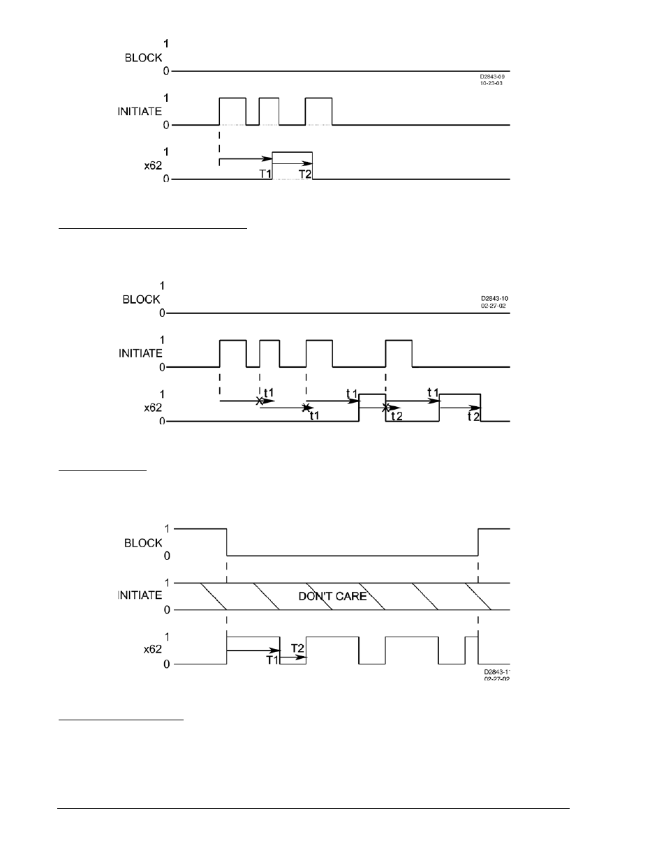
Figure 4-39. Mode 2, One-Shot Nonretriggerable Timer
Mode 3, One-Shot Retriggerable Timer
This mode of operation is similar to the one shot nonretriggerable mode, except that if a new FALSE-to-
TRUE transition occurs on the INITIATE input expression, the output is forced to logic FALSE and the
timing sequence is restarted. See Figure 4-40.
Figure 4-40. Mode 3, One Shot Retriggerable Timer
Mode 4, Oscillator
In this mode, the INITIATE input is ignored. See Figure 4-41. If the BLOCK input is FALSE, the output,
x62, oscillates with an ON time of T1 and an OFF time of T2. When the BLOCK input is held TRUE, the
oscillator stops and the output is held OFF.
Figure 4-41. Mode 4, Oscillator
Mode 5, Integrating Timer
An integrating timer is similar to a pickup/dropout timer except that the PICKUP time T1 defines the rate
that the timer integrates toward timing out and setting the output to TRUE. Conversely, the RESET time
T2 defines the rate that the timer integrates toward dropout and resetting the output to FALSE. PICKUP
time T1 defines the time delay for the output to change to TRUE if the initiate input becomes TRUE and
stays TRUE. RESET time T2 defines the time delay for the output to change to FALSE if it is presently
TRUE and the initiate input becomes FALSE and stays FALSE.
4-44
BE1-700 Protection and Control
9376700990 Rev M