Basler Electric BE1-700 User Manual
Page 85
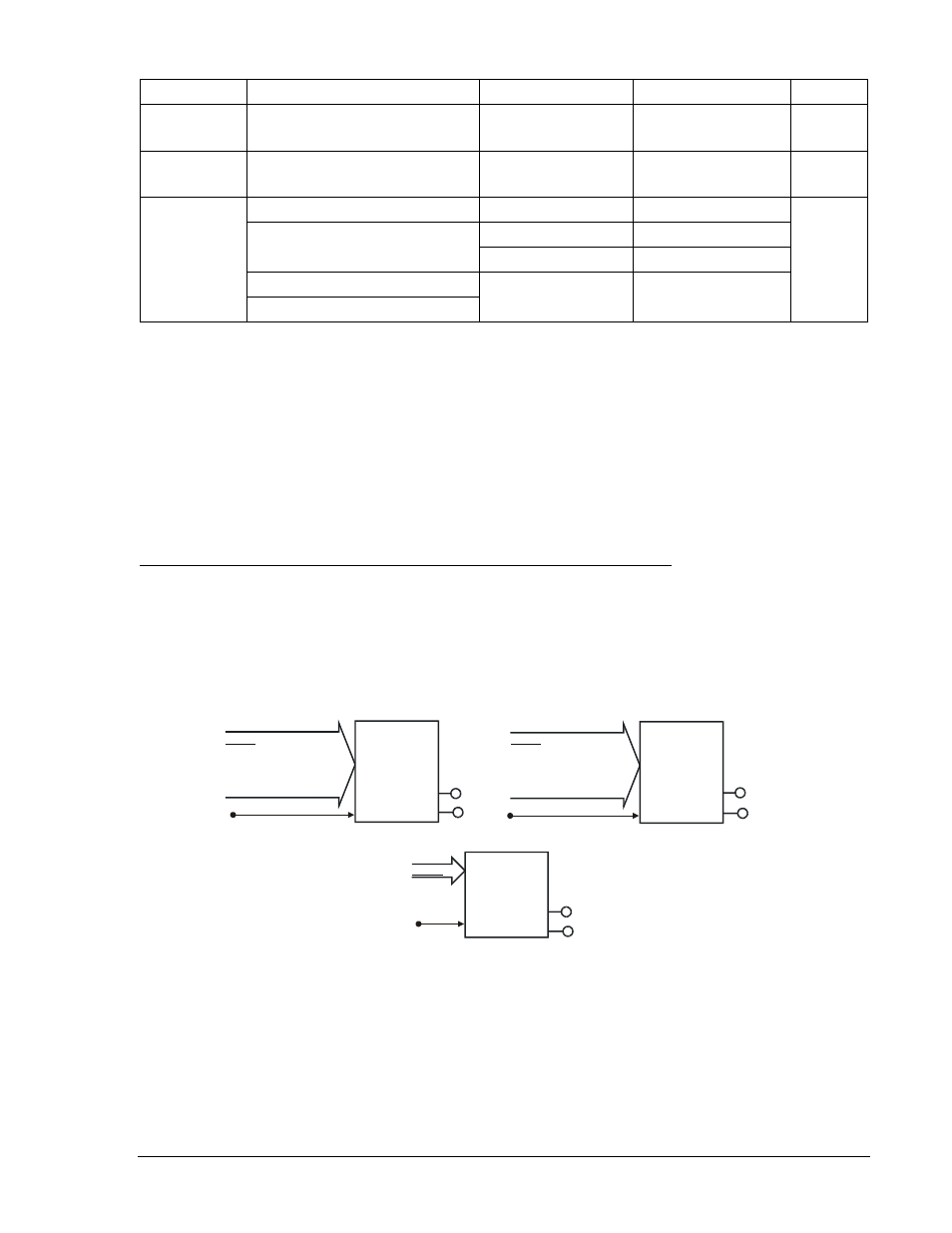
Table 4-17. Operating Settings for Phase Undervoltage/Overvoltage Protection
Setting
Range
Increment
Unit of Measure
Default
Pickup
0 = Disabled
10 to 300
0.1 for 0 to 99.9
1.0 for 100 to 300
Secondary Volts †
0
Inhibit
27 only
0 = Disabled
10 to 300
0.1
Secondary Volts †
0
Time Delay
50 to 999 milliseconds
1
Milliseconds
50 ms
1 to 600 seconds
0.1 for 1.0 to 9.9
Seconds
1.0 for 10 to 600
Seconds
3 to 36,000 cycles (60 Hz)
∗
Cycles
2.5 to 30,000 cycles (50 Hz)
∗ Time delays less than 10 cycles can be entered to the nearest 0.1 cycles from the front panel HMI. All
time delays can be entered to the nearest 0.01 cycles from the ASCII command interface. Time delays
entered in cycles are converted to milliseconds or seconds. Increment precision after conversion is
limited to that appropriate for each of those units of measure.
† Unit of measure is secondary VPP or secondary VPN depending on the VTP connection settings.
Time delay settings entered in cycles are converted to seconds or milliseconds (per the nominal
frequency setting stored in EEPROM) before being stored. See Section 3, Input and Output Functions,
Power System Inputs, Voltage Measurement, for more information about this setting. If the nominal
frequency setting is being changed from the default (60 hertz) and time delay settings are being set in
cycles, the frequency setting should be entered and saved before making any time delay settings
changes.
Retrieving Phase Undervoltage/Overvoltage Protection Status from the Relay
The status of each logic variable can be determined through the ASCII command interface using the RG-
STAT (report general-status) command. See Section 6, Reporting and Alarm Functions, General Status
Reporting, for more information. The status can also be determined using BESTCOMS Metering screen.
27X/59X - Auxiliary Undervoltage/Overvoltage Protection
Figure 4-25 illustrates the inputs and outputs of the auxiliary under/overvoltage elements. Element
operation is described in the following paragraphs.
Figure 4-25. Auxiliary Undervoltage/Overvoltage Logic Blocks
The auxiliary elements have two outputs: 27/59XPU (pickup) and 27/59XT (trip). When the monitored
voltage increases above the pickup setting, the pickup output becomes TRUE and the element starts
timing toward a trip. The trip output becomes TRUE when the element timer times out.
The BLK (Block) input is used to disable protection. A BESTlogic expression defines how the BLK input
functions. When this expression is TRUE, the element is disabled by forcing the outputs to logic 0 and
resetting the timer. This feature functions in a similar way to the torque control contact of an
electromechanical relay.
D2871-21
05/13/02
159XT
159XPU
BLK
159X
Mode
BLK
27XT
27XPU
AUX
UNDER-
VOLTAGE
(27X)
Mode
0-Disable
1-Fundamental Vx Input
2-3VO - 3ph VT Input
3-Harmonic Vx Input
BLK
59XT
59XPU
AUX
OVER-
VOLTAGE
(59X)
Mode
0-Disable
1-Fundamental Vx Input
2-3VO - 3ph VT Input
3-Harmonic Vx Input
9376700990 Rev M
BE1-700 Protection and Control
4-29