Basler Electric BE1-700 User Manual
Page 217
source and another element from a low side or distribution source. Output of the two elements is
connected through an AND gate thus requiring both underfrequency elements to pickup before providing
a trip output. Dual source sensing helps to ensure operation for true system underfrequency events.
The following application tips detail examples of a
Abus@ and Acircuit level@ underfrequency load shed
scheme and restoration
Apermissive@ using dual source sensing and the programming capabilities of the
BE1-700V. (Single source sensing can also be used.) These schemes are easily customized to meet the
user
=s specific requirements.
Bus Level Application
The following logic was designed to work with the preprogrammed BUS Logic Scheme described
elsewhere in this section.
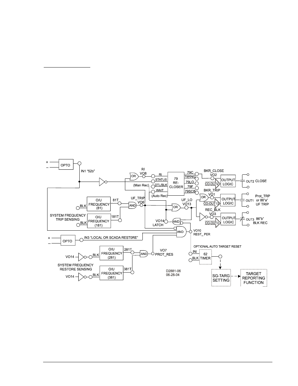
Referring to Figure 8-14, if sensing voltage is above the inhibit setting, and system frequency below the
81 and 181T setting, UF_TRIP, VO6 will go high. This in turn forces VO3 (UFLO_TRP) high, closing
Output 3 Contact and tripping the user lockout(s) (86) devices and, in turn, tripping the associated
breakers. When the
Aload condition@ that caused the underfrequency event has subsided, the system
operator/dispatcher will initiate a remote restoration procedure. A
Arestoration permissive@ from the BE1-
700 verifies that the following conditions are met prior to restoring load:
• The underfrequency trip (81and 181T) is no longer present.
• The 86UF(s) is/are tripped.
• Sensing voltage is above the predetermined inhibit level.
• System frequency is above the predetermined restore level (281 and 381T)
Figure 8-14. Underfrequency Load Shed, Circuit Level Application, Manual or Auto Close from SCADA or
Local Restore
The first two conditions must be met to remove REST_BLK from the 281 and 381T overfrequency
elements. Then, with sensing voltage above the inhibit setting of 281 and 381T and the system frequency
above the 281 and 381T setting, VO10 (REST_PER) will go high forcing VO4, UFLO_RES high, closing
Output Contact 4. As long as these conditions remain unchanged the Output Contact 4 will remain
closed. When the last 86UF (electrical reset lockout relay) is reset, Input 1, UF_RESTORE will go low,
blocking the 281 and 381T elements. Also, VO4 will go low, opening Output Contact 4, removing the
86UF Restore Permissive. The last 86UF to reset can initiate an optional
Aauto target reset circuit@, thus
eliminating the need for further operator input. A one-shot, non-retriggerable timer (62) initiated by the last
9376700990 Rev M
BE1-700 Application
8-35