Table 6-3. logic variable status report format -4 – Basler Electric BE1-700 User Manual
Page 136
Output (A12345)
Output contact status for OUTA, OUT1, OUT2, OUT3, OUT4, and OUT5 is reported on this line. This
information is also available at HMI Screen 1.5.2. “0” indicates a de-energized output and “1” indicates an
energized output. More information about output contact operation is available in Section 3, Input and
Output Functions.
CO-OUT (A12345)
This line reports the logic override of the output contacts. Logic override status is also reported at HMI
Screen 1.5.3. Section 3, Input and Output Functions, provides more information about output logic
override control.
CO-43/143
Virtual switch function status is reported on this line. This information is also available at HMI Screen
1.5.4. See Section 4, Protection and Control, Virtual Switches, for more information about virtual switch
operation.
CO-101 (101SC)
This line reports the status of the virtual breaker control switch slip contact output. More information about
the virtual breaker control switch is available in Section 4, Protection and Control, Virtual Switches.
CO-Group
The logic override status of the setting group selection function is reported on this line. For more
information about this function, refer to Section 4, Protection and Control, Setting Groups.
Active Logic
This line reports the name of the active logic scheme. The active logic scheme name can also be viewed
at HMI Screen 5 and through the SL-N command. See Section 7, BESTlogic Programmable Logic, for
more information about this function.
Recloser (79) (Optional)
The status of the recloser is reported on this line. HMI Screen 1.1 also reports this information. More
information about the recloser function is available in Section 4, Protection and Control.
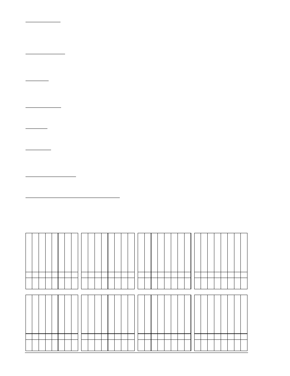
Logic Variables (00-31), (32-63), and (64-95)
These three lines report the status of each BESTlogic variable. These lines can be entered into Table 6-3
to determine the status of each logic variable. Section 7, BESTlogic Programmable Logic, provides more
information about BESTlogic variables. This information is not available through the HMI.
Table 6-3. Logic Variable Status Report Format
5
0
T
P
T
1
5
0
T
P
T
5
0
T
N
T
1
5
0
T
N
T
5
0
T
Q
T
1
5
0
T
Q
T
5
1
P
T
S
P
A
R
E
5
1
N
T
1
5
1
N
T
5
1
Q
T
5
0
T
P
P
U
1
5
0
T
P
P
U
5
0
T
N
P
U
1
5
0
T
N
P
U
5
0
T
Q
P
U
5
0
T
Q
P
U
5
1
P
P
U
S
P
A
R
E
5
1
N
P
U
1
5
1
N
P
U
5
1
Q
P
U
4
3
1
4
3
7
9
P
7
9
C
7
9
R
N
G
7
9
L
O
7
9
R
S
T
7
9
S
C
B
S
P
A
R
E
L
O
G
I
C
0
0
0
0
1
0
2
0
3
0
4
0
5
0
6
0
7
0
8
0
9
1
0
1
1
1
2
1
3
1
4
1
5
1
6
1
7
1
8
1
9
2
0
2
1
2
2
2
3
2
4
2
5
2
6
2
7
2
8
2
9
3
0
3
1
V
O
A
V
O
1
V
O
2
V
O
3
V
O
4
V
O
5
V
O
6
V
O
7
V
O
8
V
O
9
V
O
1
0
V
O
1
1
V
O
1
2
V
O
1
3
V
O
1
4
V
O
1
5
I
N
1
I
N
2
I
N
3
I
N
4
6
2
1
6
2
2
7
X
T
2
7
X
P
U
1
0
1
T
1
0
1
C
1
0
1
S
C
A
L
M
L
G
C
A
L
M
M
A
J
A
L
M
M
I
N
O
U
T
1
M
O
N
T
R
S
T
K
E
Y
3
2
3
3
3
4
3
5
3
6
3
7
3
8
3
9
4
0
4
1
4
2
4
3
4
4
4
5
4
6
4
7
4
8
4
9
5
0
5
1
5
2
5
3
5
4
5
5
5
6
5
7
5
8
5
9
6
0
6
1
6
2
6
3
6-4
BE1-700 Reporting and Alarm Functions
9376700990 Rev M