Negative-sequence overcurrent protection, 46 curve -17, Negative-sequence overcurrent protection -17 – Basler Electric BE1-700 User Manual
Page 73: Negative-sequence pickup settings -17, Figure 4-12. curve coefficients -17
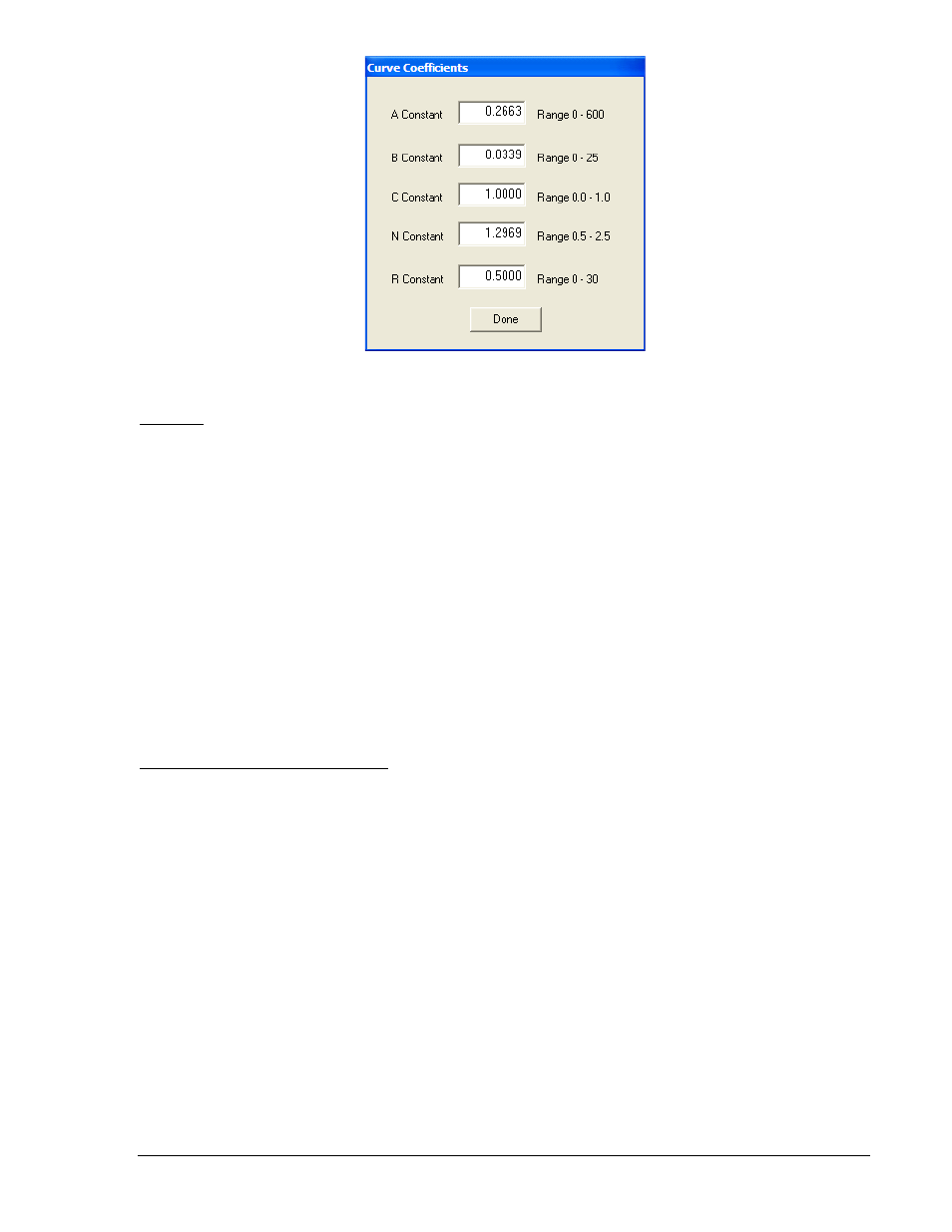
Figure 4-12. Curve Coefficients
46 Curve
The 46 curve is a special curve designed to emulate the I
2
t withstand ratings of generators using what is
frequently referred to as the generator’s K factor. Do not confuse the 46 curve with the 46 element. The
46 curve was designed for use with the 46 function. But, in actuality, the 46 curve may be selected for use
with the 51P, 51N, and 51Q protection functions as well (though in actual practice, it is doubted that this
will be done very often).
To use the 46 curve, the user should determine the K factor of the generator and the continuous (I
2
)
2
t
rating of the generator (supplied by the manufacturer) and use this to set the time dial and pickup for the
46 curve by the process described in Appendix A, Time Overcurrent Characteristic Curves. The K factor
is the time the generator can withstand 1 per unit I
2
where 1 pu is the relay setting for nominal current.
Negative-Sequence Overcurrent Protection
For years, protection engineers have enjoyed increased sensitivity to phase-to-ground unbalances with
the application of ground relays. Ground relays can be set more sensitively than phase relays because a
balanced load has no ground (3
I0
) current component. The negative-sequence elements can provide
similar increased sensitivity to phase-to-phase faults because a balanced load has no negative-sequence
(I
2
) current component.
Negative-Sequence Pickup Settings
A typical setting for the negative-sequence elements might be one-half the phase pickup setting in order
to achieve equal sensitivity to phase-to-phase faults as three-phase faults. This number comes from the
fact that the magnitude of the current for a phase-to-phase fault is
√3/2 (87%) of the three-phase fault at
the same location. This is illustrated in Figure 4-14.
The phase-to-phase fault is made up of both positive and negative-sequence components as shown in
Figure 4-13 or a phase-to-phase fault, the magnitude of the negative-sequence component is 1/ 3 (58%)
of the magnitude of the total phase current. When these two factors (
√3/2 and 1/√3) are combined, the √3
factors cancel which leaves the one-half factor.
9376700990 Rev M
BE1-700 Protection and Control
4-17